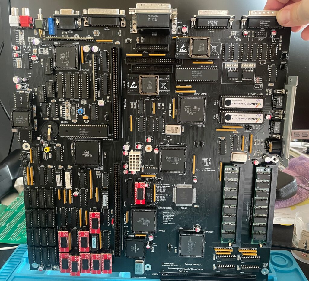
This is an amazing replica of the Commodore A2386SX PC bridgeboard, you can find out more about the project here. There is also a discussion forum about the card on the German A1K forum (just use auto translate in your browser if you dont speak German).
Background
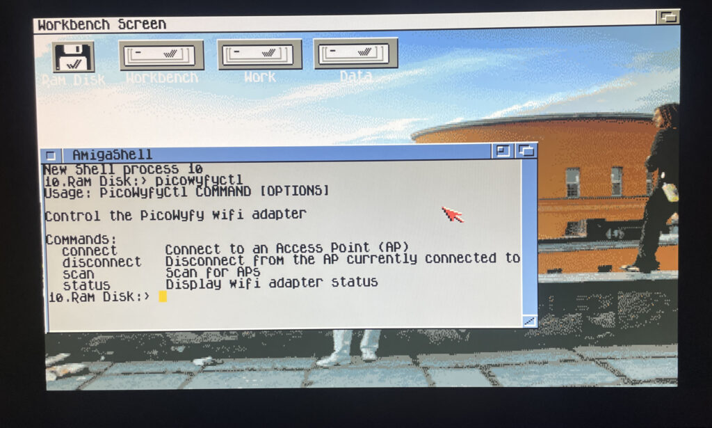
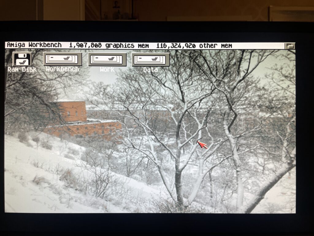
The A2386SX was the best PC bridgeboard Commodore made for the Amiga, it was based on a 386 CPU, could be expanded to 8 MB and enabled you to transform an Amiga in a multi CPU system that could run tasks in parallell on both CPUs, one in Amiga Workbench and the other in MS-DOS on the bridgeboard – at the same time. You could for example hop in to MS-DOS and run your programs and then multitask back to Workbench while programs where running in both environments.
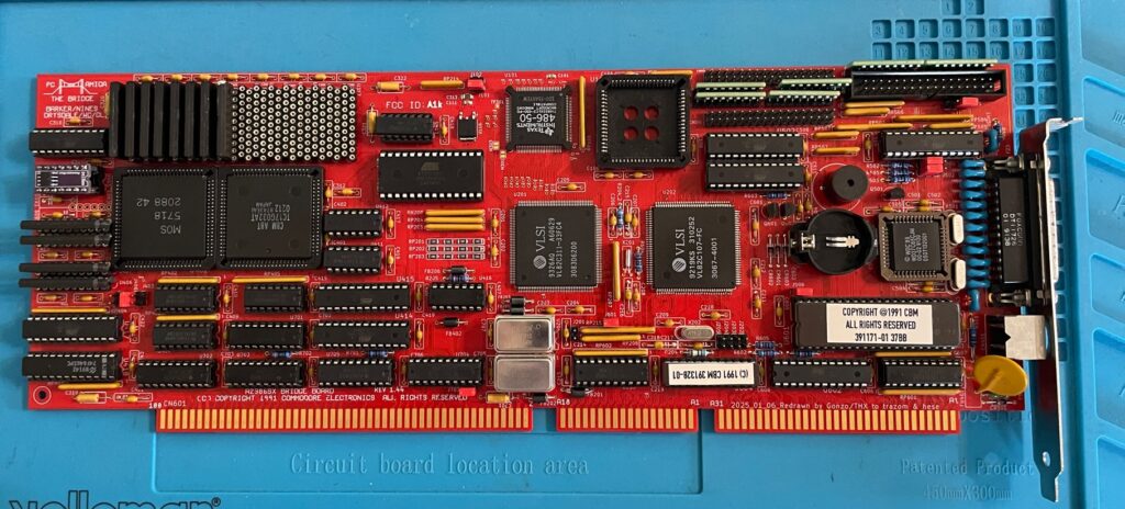
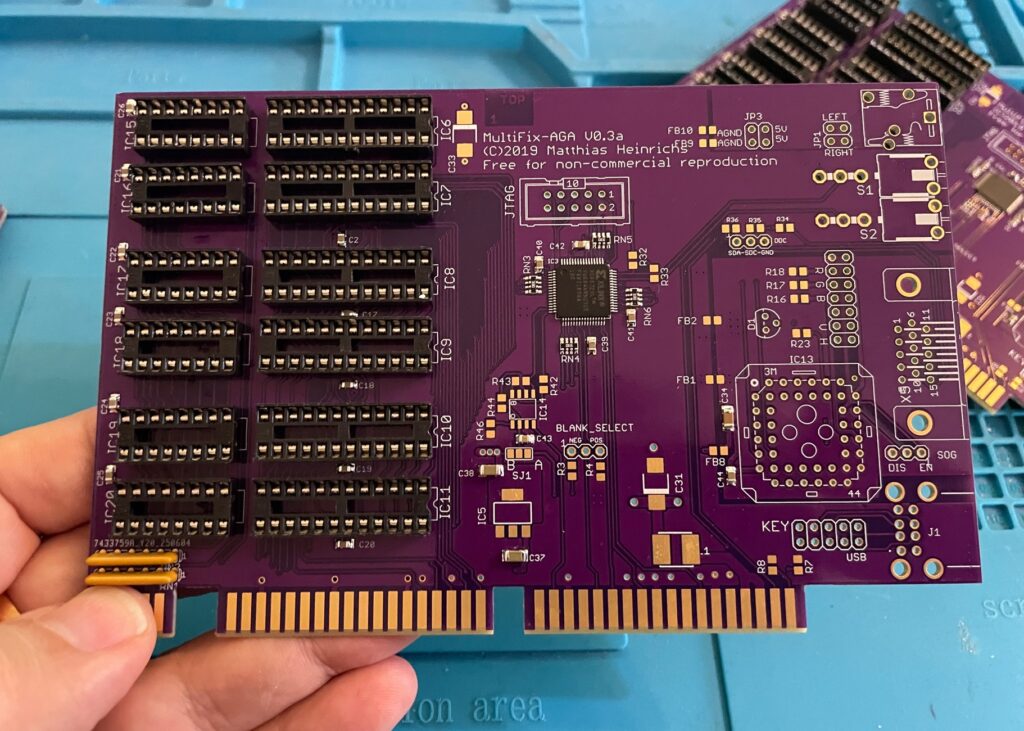
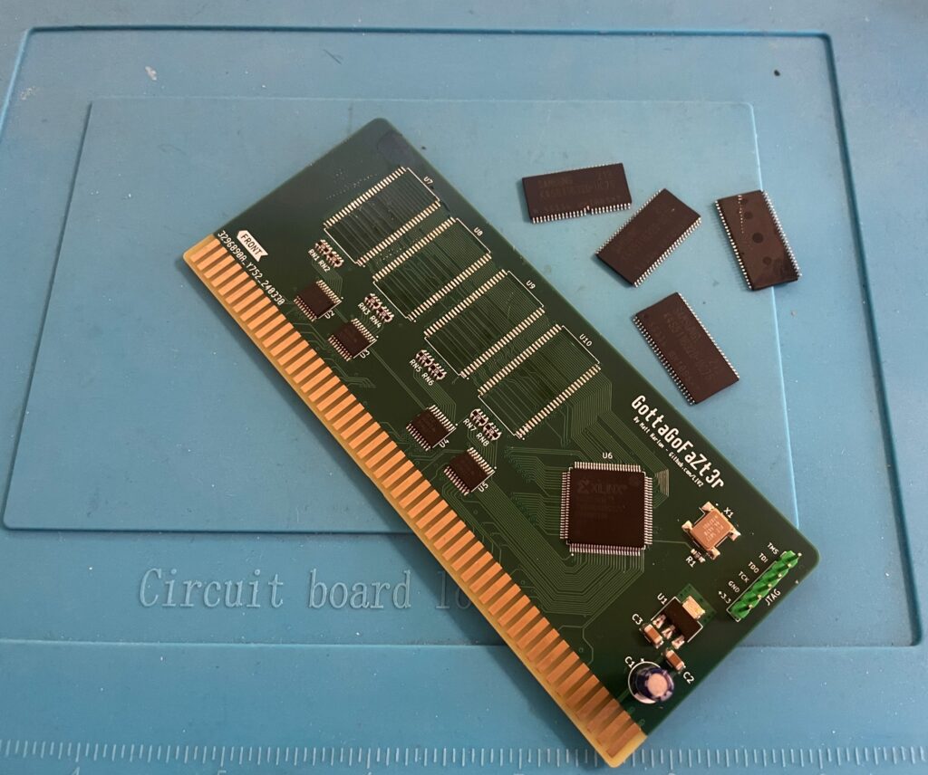
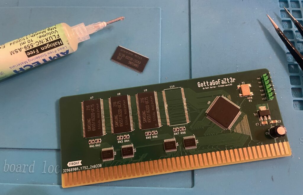
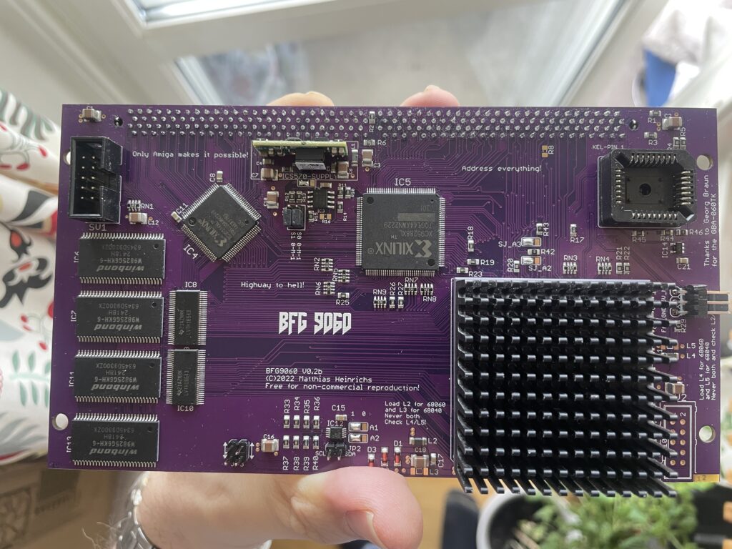
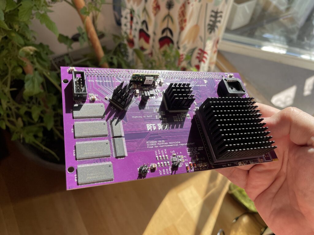
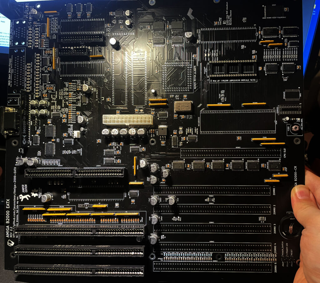
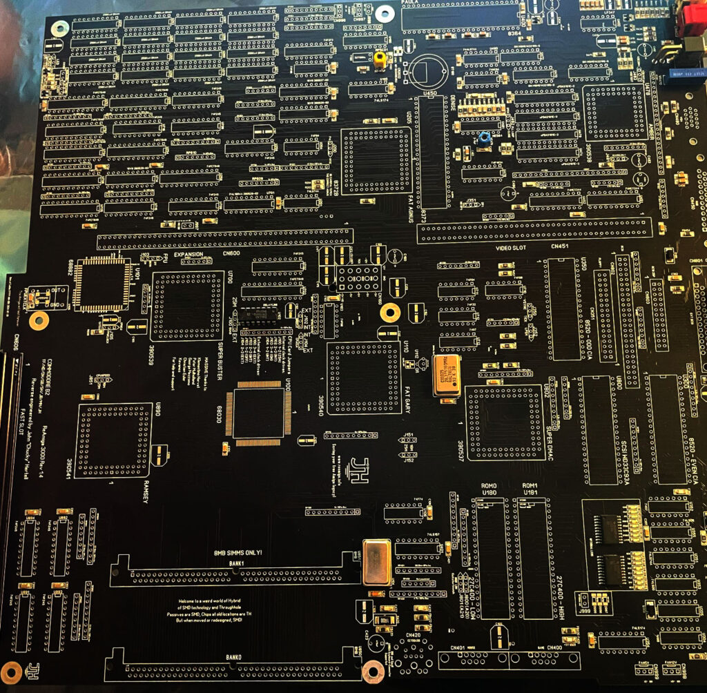
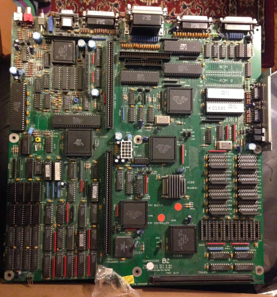
This is a beautiful built replica of the A2386SX PC bridgeboard by Commodore.
I got my PCB late in Q1 after contemplating if it was even possible for me to build this card at all. The main problem was finding all the parts and programming some of the chips. But I quickly came to realization that it was actually possible to locate almost all the parts if I pulled the trigger at the right moment.
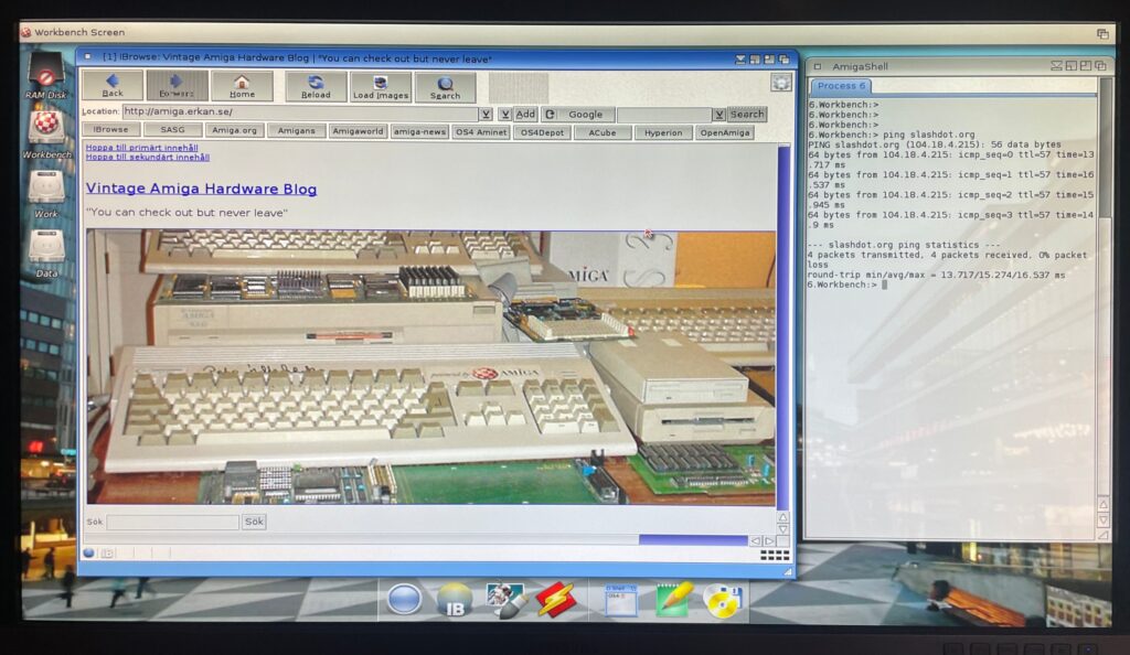
My main goal of running the card is to have access to multi channel module players such as Cubic Player and to be able to play PC modules in MS-DOS with a Sound Blaster 16. I would also like to dive into some old MS-DOS applications I used to use 30 years ago and play some old DOS game or two. But the main attraction is PC music without having to get a separate PC for that.
Some notes on parts and building the A2386SX project
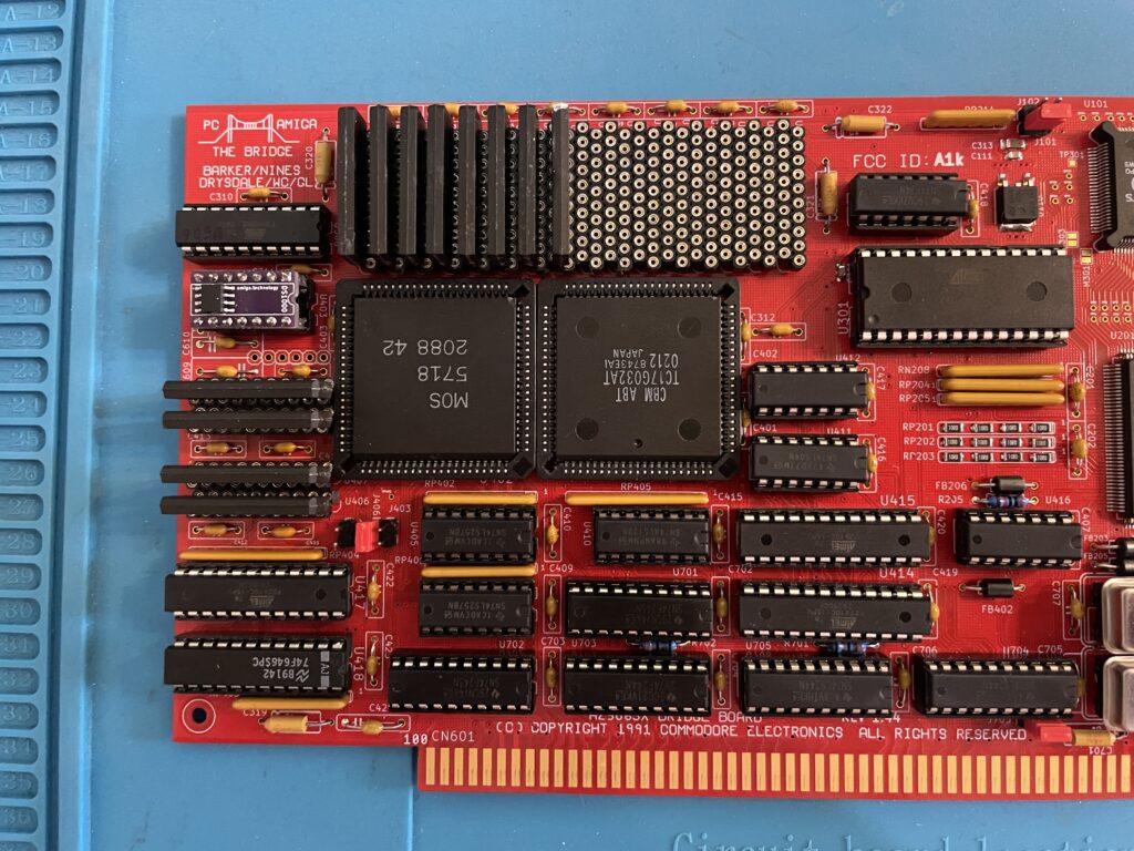
There are some very rare parts required for the A2386SX bridgeboard. The rarest chips are the two socketed PLCC84 Commodore chips and the PC chipset in the middle of the card.
The Commodore chips can be taken from 2088 and 2286 Bridgeboards (they are the same), they might pop up on eBay, but consider that a miracle if they show up. I got my chips from a cheap 2088 that I bought second hand last year. Did not know what to do with it at the time, but it was too cheap to pass up on and I am glad about that now.
The PC chipset should in theory be easy to find online, but so far, I have only been able to locate one of the chips. The other chip needs to be ordered in bulk from a specialist in rare chips and is costly (and will probably only go up in price). I thought it was possible to find an old motherboard and desolder them from there, if you find a motherboard that has them – consider that a miracle!
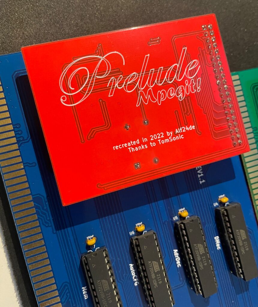
Then we have other obscure chips such as the floppy controller, programmable chips (that needs a special vintage programmer or someone with better skills than me in understanding how to program them with a modern device) – not really a problem to find.
Memory can be found from obscure part specialists (remember you need two types of memory). The CPU is available on eBay, but if you want the faster 486 that is compatible with the card, good luck, as said, miracles can happen!
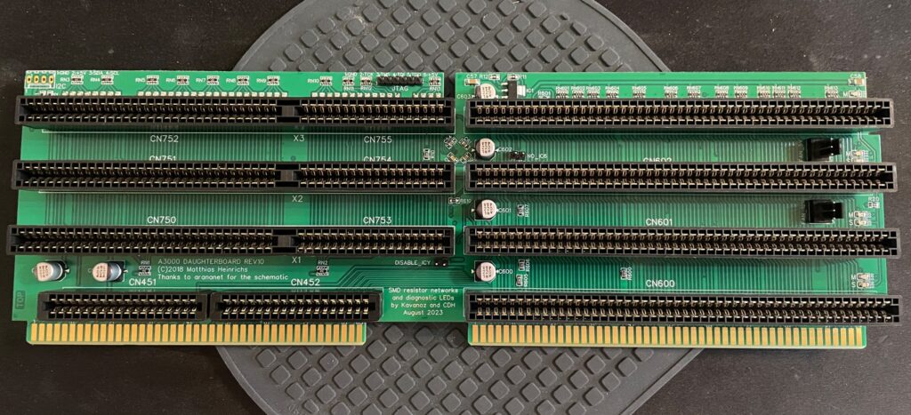
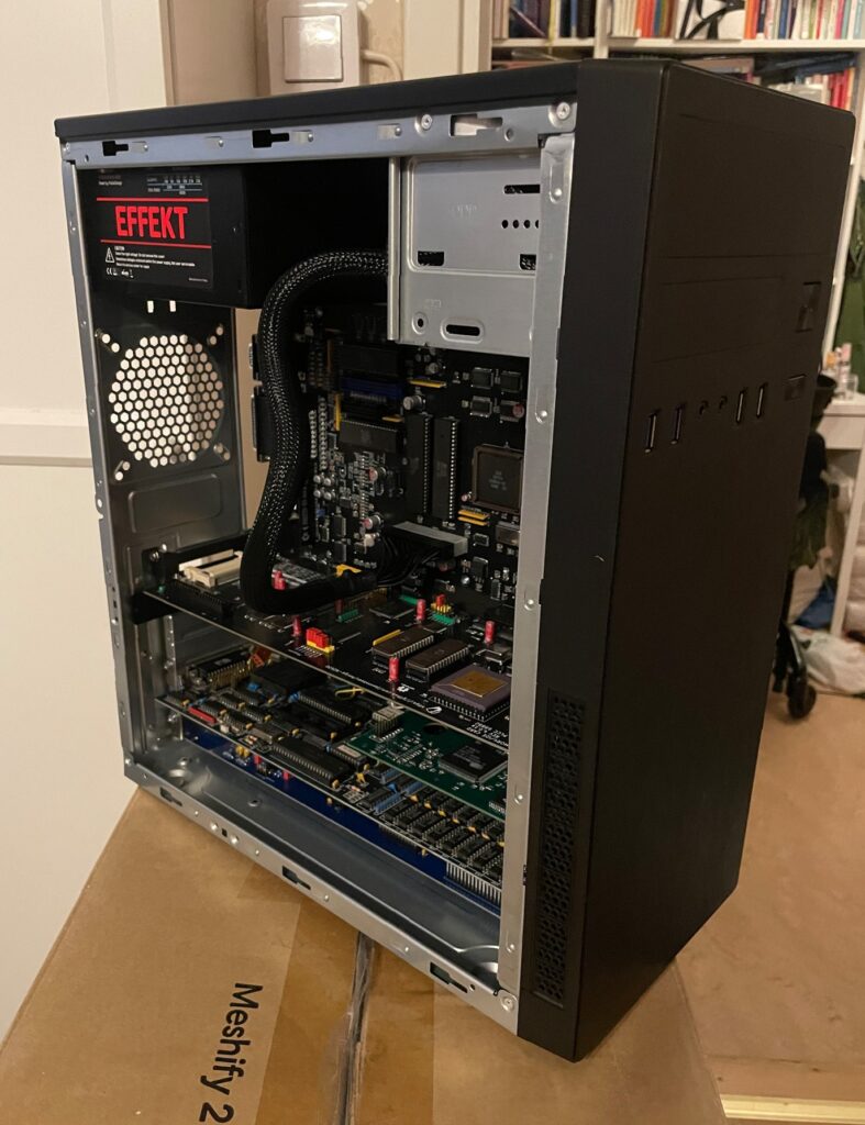
Bracket was sourced from another enthusiast who ordered a batch. 646 was taken from my donor A3000.
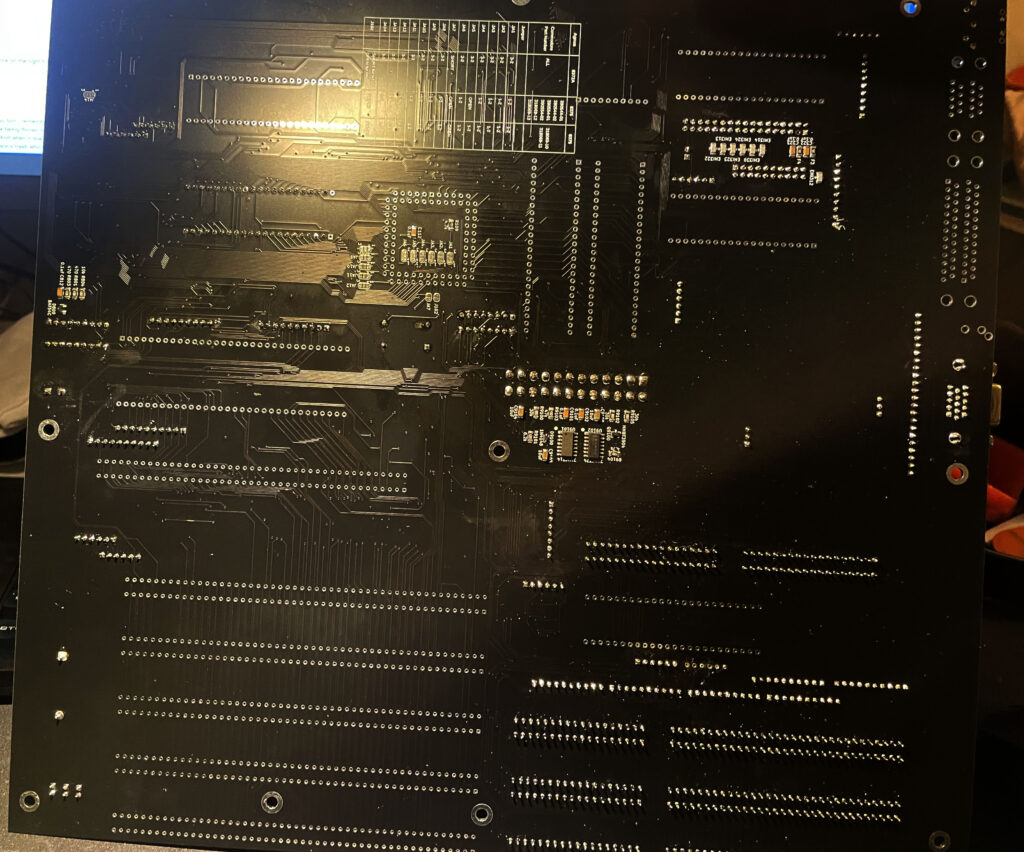
Full socket build
I did a full socket build, thinking it would make it easy to error check or replace chips.
486 chip instead of 386 chip
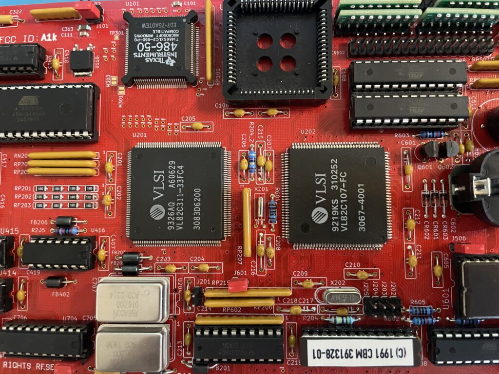
So while this is a 386 bridgeboard it uses a 486. I did some research earlier this year when I built my card, unfortunately I have forgotten the exact details, but it is possible to use a special 486 CPU on the board as they are the same size. I think what is most important is that the voltage level is the same as the 386 that it is supposed to use and you need to fiidle with the BIOS.
This mod works on the original Commodore A2386SX card also. This is a nobrainer for me since I grew up on 486 PCs.
Failed test run and successful test run!
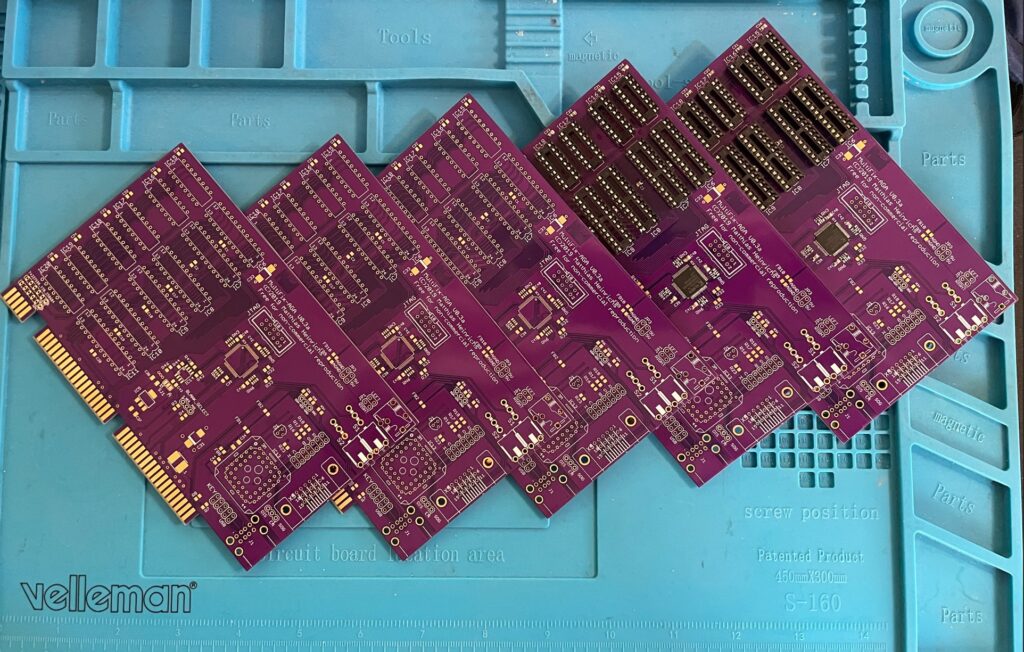
So after having received more than 10 packages from around the world and a the main passives from Mouser I decided to build it up.
I was super excited to do the first test run after receiving the programmed chips. Bummer – But the first test run failed – the card refused to run!
Most of my projects I build usually run fine, if there are any errors it is usually a bad solder joint on a surface mounted component. In this case I knew I would never figure it out myself, so I sent it off to a friend in the hobby to get it checked.
Turned out that I had used the wrong memory (I had used the memory from my donor Amiga 3000), there was also an error in the BOM that has since been updated where bussed resistor nets where specified instead of isolated (or was it vice versa).
Once I received the card I did another test run and could confirm the card to be fully running!
And then I realized, its going to take a shitload of time setting the card up.
Next steps
I probably did not realise how much work it would be to set this card up so thats why I will do it after summer. But the plan is to get MS-DOS 6.22 up and running with Windows 3.1. I will run an ISA graphics card and an ISA sound card and will also try to run the HDD off a partition on the Amiga HDD.
Would also love to build a second card, hopefully there will be an up to date model with chips replaced with CPLDs!