I finally got my hands on the PowerShark Power Adapter for the Amiga 500/600/1200. There are many PSU options for wedge Amigas these days but the PowerShark power adapter in combination with a USB-C PSU for the Amiga was a nobrainer for me to choose because of two reasons: It is USB-C and it has a power switch close to the Amiga 1200.
USB-C Amiga PSU
I highly suspect USB-C will become even more widespread in the future for retro gear, not just for Amiga computers. I suspect most vintage hardware will be able to be modded or will be able to made run on USB-C with some hardware device – meaning, one main PSU could drive many devices instead of having multiple aging PSUs.
The power switch situation
Having a power switch close to the Amiga is a luxury. No need to reach for the switch on the floor anymore.
Lets take a closer look at the PowerShark Power Adapter for Amiga
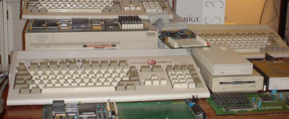
Top of the PowerShark Power Adapter, notice the USB-C socket in the mouth of the shark
The PowerShark power adapter is a neat little piece of hardware that inserts into the power socket on the Amiga 500, 600 or 1200. It has a LED that lights up in either red or green, red if the PSU driving it fails or green if everything works. The plastic shell is quite nice and looks professional.
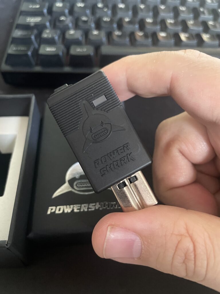
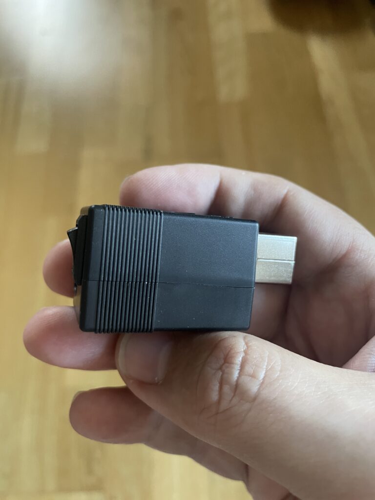
Back of the PowerShark Amiga USB-C Power Adapter
The backside of the PowerShark power adapter for the Amiga has a small on/off switch and the USB-C socket for powering it from the USB-C PSU.
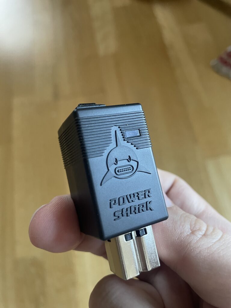
Sideview of the PowerShark Amiga PSU USB-C Power Adapter
The side view shows its small size. The size of the PowerShark is 25 x 27 x 58mm.
How to power the PowerShark Power Adapter for the Amiga?
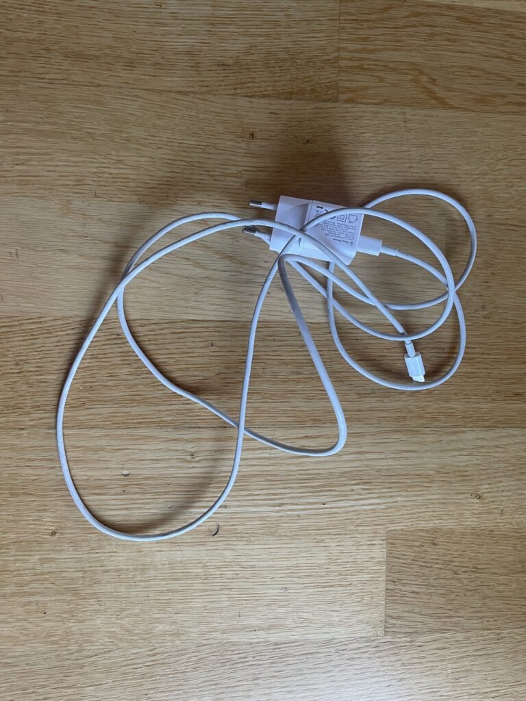
A regular USB-C phone charger PSU and an old Apple USB-C Macbook charging cable
The PowerShark has to be fed power from a USB-C PSU. As you may know Amiga runs on different voltages so PowerShark Power Adapter has to be fed 12v. The 12v then gets converted into the different voltages the Amiga needs to run in the PowerShark. That means the USB-C PSU has to provide 12v or else it wont work.
Besides providing 12v the PSU has to provide enough amps or else there wont be enough power to power up the A1200 (a 5w phone USB-C charger wont run an A1200).
I tried with my laptop charger and it did not work because it did not provide 12v. But another USB-C laptop charger I had worked fine since it could provide 12v. If in doubt, it is usually specified on the charger if the USB-C PSU outputs 12v.
I also tried with a low end Apple charger (5-7w IIRC) and that did not work either as expected, the PowerShark just got a red LED.
For testing purposes I fell back on this 20w USB-C phone charger i found at home pictured above. I will for sure upgrade to a more beefy USB-C PSU later but for now this will do fine.
There are some details on the homepage about the USB-C cable that you should use. I just took the safe route here and used an old Apple USB-C cable that powered an old Apple laptop i had years ago.
A nice cheap alternative is to get the RaspberryPi 5 27w USB-C PSU. But that one seems not to be available in black.
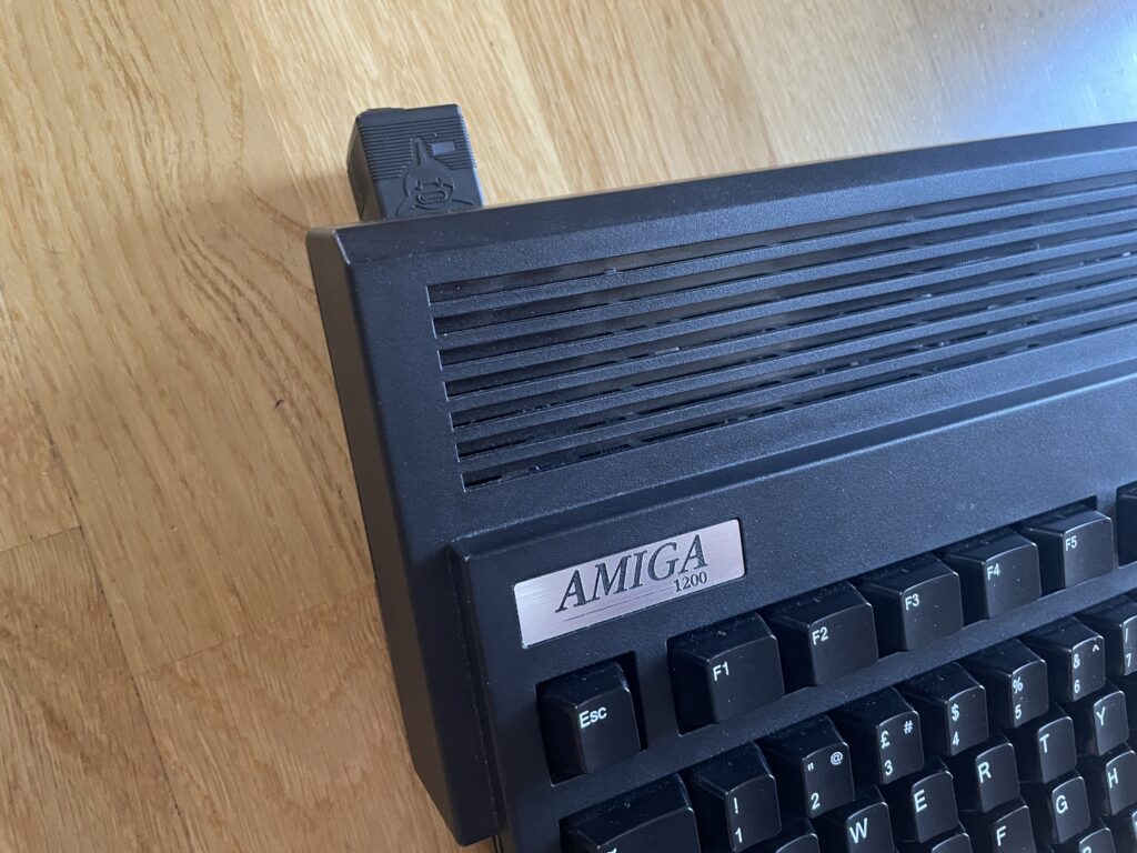
PowerShark USB-C Power Adapter on my Amiga 1200
As my main Amiga 1200 is black I wanted a black PowerShark and I think it goes well together with it. It sticks out a bit at the back but it is not that bad I think.
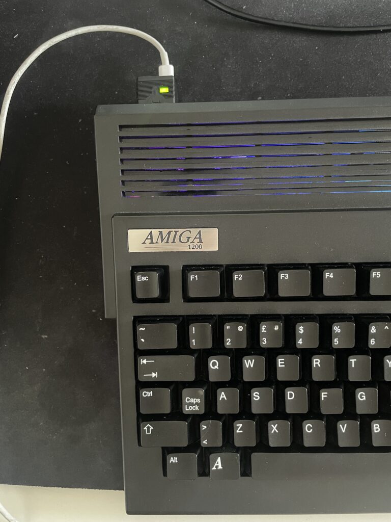
PowerShark USB-C Power Adapter on my Amiga 1200 powered on and running fine
The Amiga 1200 I used for testing consists of the following hardware and is my main A1200 (and the Amiga that gets the most use by me except the A4000TX):
ReAmiga1200 1.5
TerribleFire 1260 128MB/060@100Mhz
Indivision MK3
Solas + one LED strip
MicroniK floppy drive
4GB Compact Flash
PicoWyfy
MouSTer + USB adapter for mouse
How much power does an Amiga 1200 use
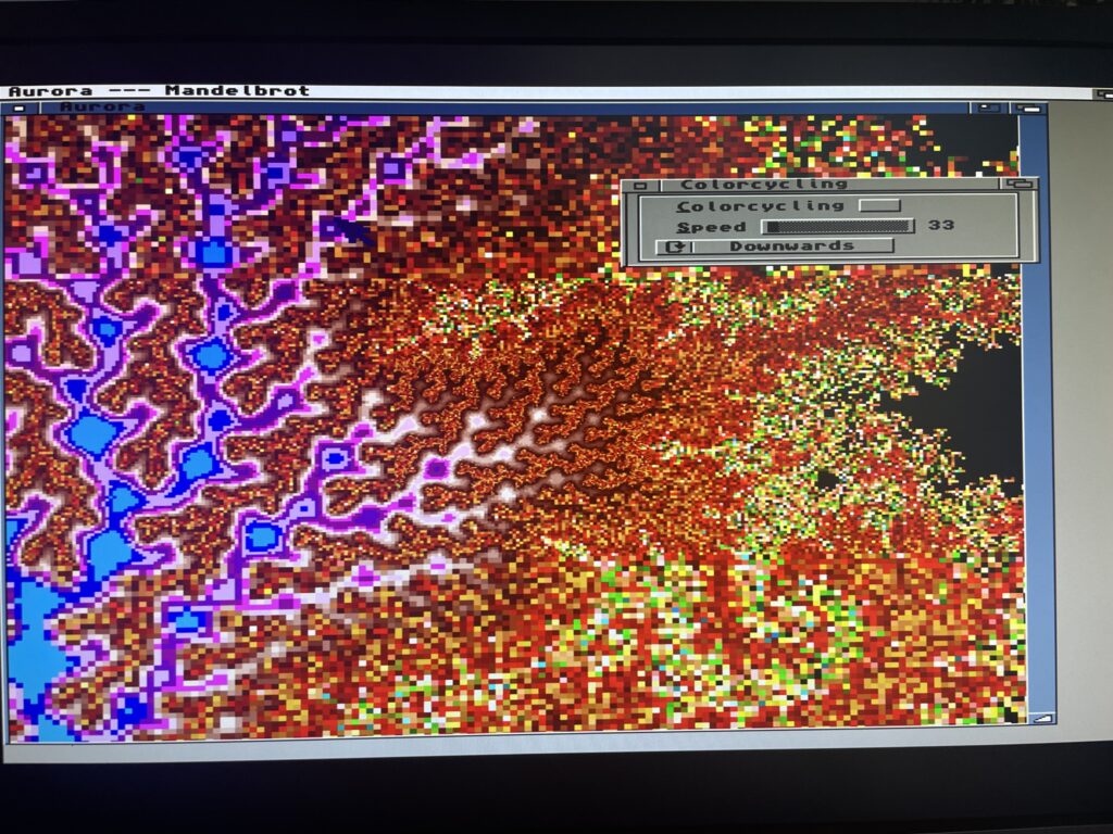
Running a fractal generator stresses the 68060 CPU a lot
I wanted to test the stability of the PowerShark and came up with a mini test. I got an idea to run a few programs that pushes the Amiga 1200 hard. I ran both Quake and Quake 2 for a few minutes and also ran a fractal generator on my A1200 with 68060. Everything worked fine – keep in mind this was not a 24h test, but more a half hour test.
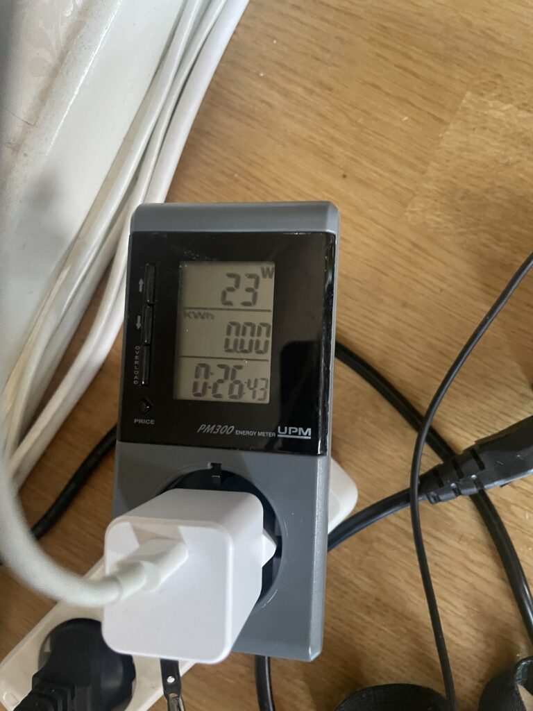
Power meter measuring the watt usage of my A1200 powered by PowerShark
I got this power meter years ago and it is quite fun measuring devices. While pushing the A1200 above hard the watt meter tops out at 23w. During idle it sits between 18-20w and during regular use around 21w.
My USB-C PSU is rated at 20w so I wont run this setup permanently as that cant be too good pushing it too hard but its interesting that stability was not an issue.
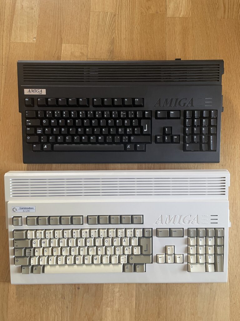
My Amiga 1200 computers, one basic one not so basic in setup
But that got me into thinking, how much power would a regular Amiga 1200 draw. I have a backup A1200 that is completely stock (except its also a ReAmiga 1.5).
This A1200 has: A CF adapter without CF card and a 3.5″ floppy drive, other than that, its completely basic.
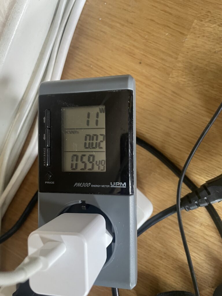
Power meter measuring the watt usage of my basic A1200 powered by PowerShark
And here it is powered by the PowerShark Power Adapter and is hovering between 9 to 11 watts.
Final thoughts
I have no regrets, this is a great addition to my Amiga 1200.
You could say it is an expensive solution since the PowerShark costs 80 euros and you need to get a USB-C PSU (and USB-C cable if PSU does not have one) so that adds to the price.
You could also say it is a complex device because you need to have a specific 12v USB-C PSU that can provide sufficient amps. There are many great options for USB-C PSUs mentioned on the website and for the average Amiga user I highly suspect this is not a real problem.
It is what it is but I think that you pay a little bit premium to have a modern solution and that is something I happily will do. I would happily pick up another one if I was knee deep in wedge Amigas only!
I got an WIFI adapter for my Sam440EP last year. Since then I have wanted to get SAMBA shares up and running on the Amiga for easy file transfers and accessing data that lives on my workstation from my Amiga.
I played around with SAMBA for Amiga as early as 1998 when I bought an Amiga 3000 with an ASDG LanRover card (for 50 euro). I never got it going though as the SAMBA archive on Aminet was confusing to follow.
How I got SMB2FS working on AmigaOS 4.1
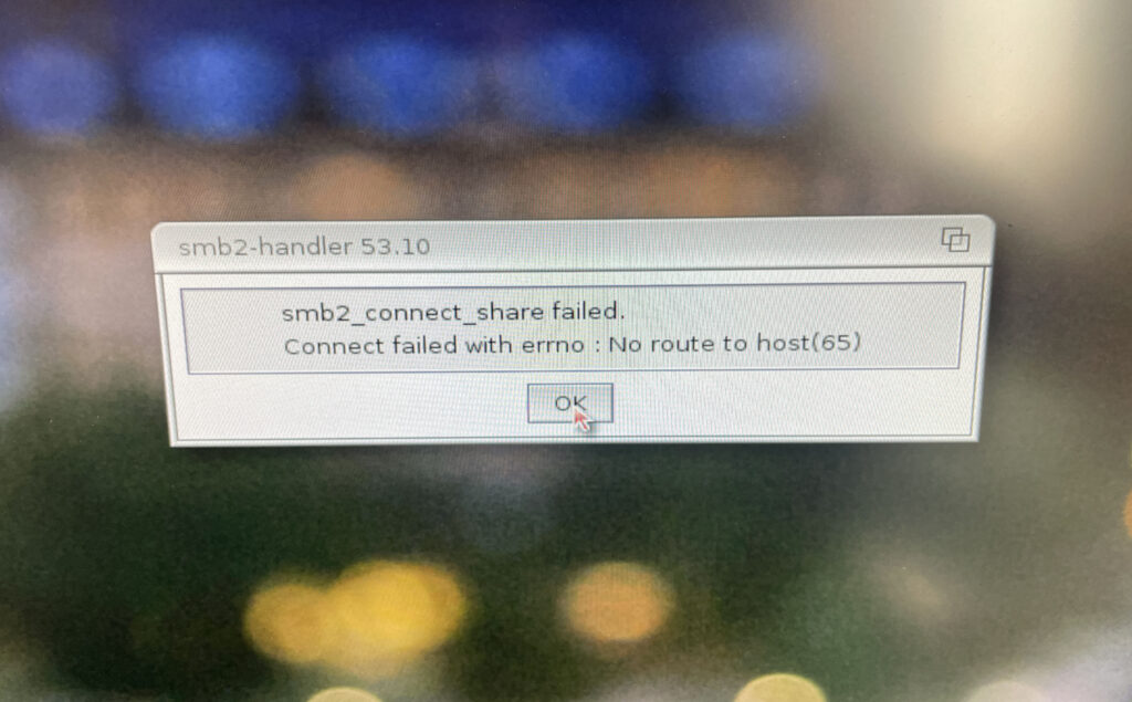
Getting SMB2FS working on AmigaOS 4.1 took a few tries…
First of all, a small disclaimer – this is how I got access to PC SAMBA shares on AmigaOS 4.1 working, it might not be the default way of doing it but it worked for me. I tried a lot of different configurations until this one worked.
Before doing the installation I recommend to double check that both machines can see each other on the network. That is done by pinging the PC from the Amiga and vice versa. To find out the IP number on the Amiga, I typed inshownetstatus in CLI. Once ping confirmed both computers shaking hands with each other, I decided to continue.
Step 1 – Download and install SMB2FS
The first thing I did was to download SMB2FS from OS4Depot. Once download I clicked on the install icon. Unlike the SAMBA installations of old on Amiga SMB2FS is much easier to setup and lets you add shares on the Amiga only. Seems like you do not have to be a Unix expert or MCSE geek to get it going anymore.
Step 2 – Adding a dosdriver for the share
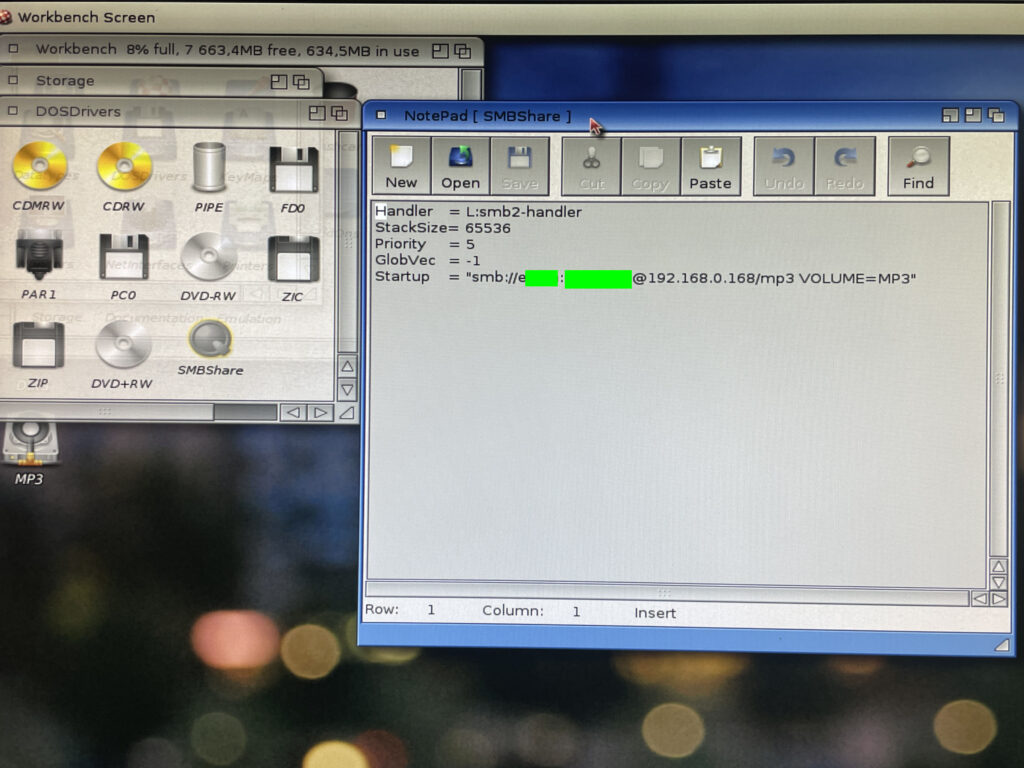
I have removed username and my password (12345678AB) from the pic above
The next thing I did after installing SMB2FS was to copy a dosdriver in sys:storage/dosdrivers. I renamed the dosdriver to SMBShare. Then I opened the dosdriver in notepad and added:
Username = The username for logging in to my workstation running Windows 11.
Password = The local password I use to log into my workstation.
Share-on-pc = The name of the folder that I shared on my workstation.
VOLUME = The name the shared volume should have in AmigaOS4
Some notes here that I would have been glad if they were specified somewere.
The username is the name you see when you open a command line on Windows.
The password has to be a local password, it wont work with a Microsoft password (the password you use for you Microsoft account).
As I understood it you should then add a default tool “c:mount” to the icon and add “activate=1” to the tooltype of the dosdriver. If you drag it over to sys:devs/dosdrivers/ and reboot then you would see the share on the desktop. But it did not for some reason work for me.
Note:
What worked was setting tooltype “activate=0” and then activating device in shell like typing in “smbshare:” (if that is what it was named to). But I wanted the share to auto mount during startup.
Step 3 – Starting the share
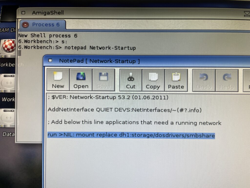
Network-Startup is like User-Startup for network applications
I got it the share to mount if I kept the dosdriver in sys:storage/dosdrivers and mounted the dosdriver from CLI by running “mount replace dh1:storage/dosdrivers/smbshare” (if you wonder why sys: is dh1:, that was an error by me during installation, off course it should be dh0:).
So I added that line to Network-Startup inside S: (not sure if you have to add run >NIL: but did not try without). During testing, I had to add replace to the mount command. Not sure why, but that is why I added it to the line here.
Step 4 – Trying out Windows 11 SAMBA share on AmigaOS 4.1
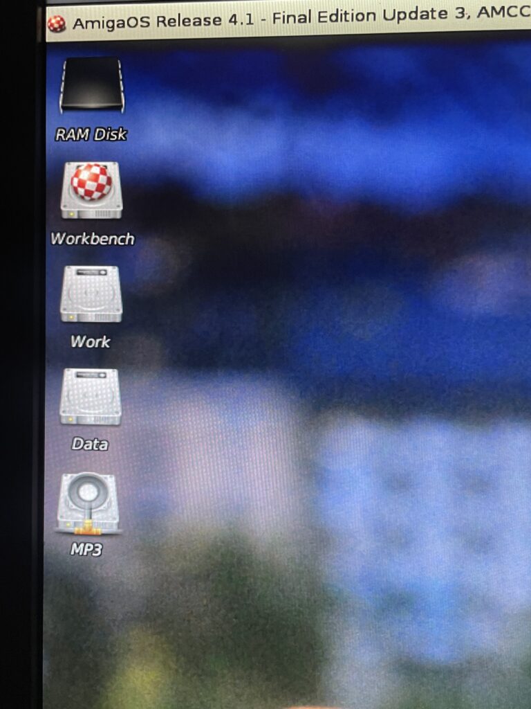
The SAMBA share is added on the Workbench desktop and behaves like a regular device
After a reboot the share popped up on Workbench! The share from the PC is the bottom device “MP3”. I have added an icon to the share otherwise it defaults to the regular AmigaOS 4.1 HDD icon. The share can be snapshotted wherever I want it on the desktop.
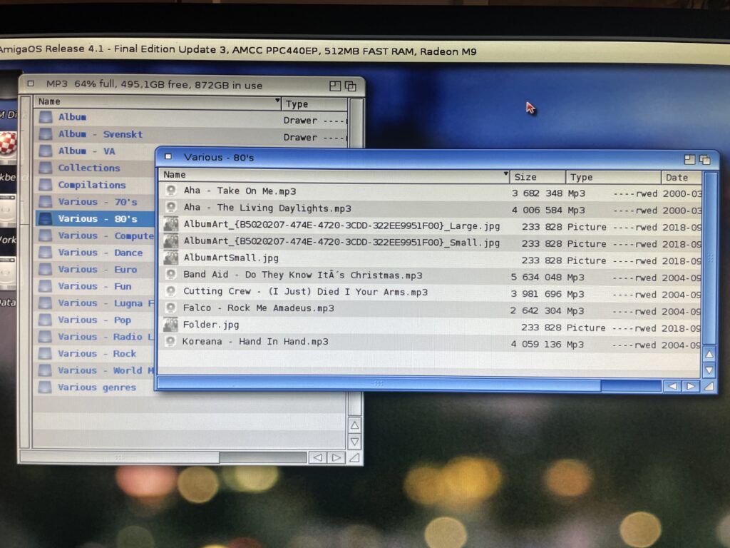
Accessing folders on the share is no different than local drawers
I have two drawers from the share open here on my AmigaOS4.1 desktop. One showing the top level of the SAMBA share and one of a sub folder. Opening folders in the share can take some time if there are many files inside them, but it is not that bad.
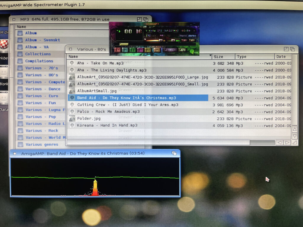
Having access to shares on another computer makes file transfers quick!
I have dragged an MP3 file to AmigaAMP that plays the tune from the share over the network. Occasionally there is some lag. I think that is because I am running a wireless adapter, but it is not that bad.
Next steps
Install SMB2FS on my 68k Amiga systems. DONE, it was almost exactly the same procedure.
I would also like to share the full Amiga partitions to my workstation, that way I would for example be able to edit s:user-startup or restructuring partitions or add/remove files from my PC.
I have been following this project with some interest from time to time but never pulled the trigger to get the relevant hardware to get a setup going.
Partly it was because I was swamped with Amiga hardware projects, partly because PPC on 68k Amigas was not really that relevant anymore – unlike yesterday when it was the next logical step for the Amiga to evolve to. Secondly, I could not wrap my head around how to set it up or where to find an affordable card.
But times change and I reconsidered that last opinion about it not being relevant when I skimmed through the supported applications a year or so ago.
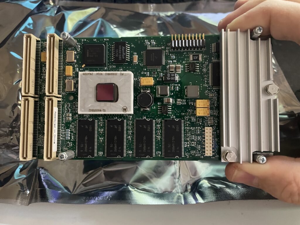
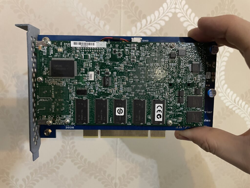
Emerson-Motorola PrPMC8005E-1259 PPC card
One supported PPC card by the initative to get PPC working on PCI Amigas is the Emerson-Motorola PrPMC8005E-1259 that I was lucky to be able to pick up for a very reasonable sum on Ebay. All I needed now was a weekend to get the this insane setup going.
The PrPMC8005E-1259 contains a 450 MHz MPC7410 G4 PPC CPU and 128 MB memory. It is a PMC card and fits a PCI card that acts as a PMC carrier on the Amiga.
Originally this CPU card is not meant to be used on an Amigas at all, I think the main use is in industrial applications and in telecommunication, but exactly how and why – No idea!
Before I continue, lets look at some previous Amiga PPC setups I toyed around with a few years ago.
Previous Amiga PPC setups, time flies…
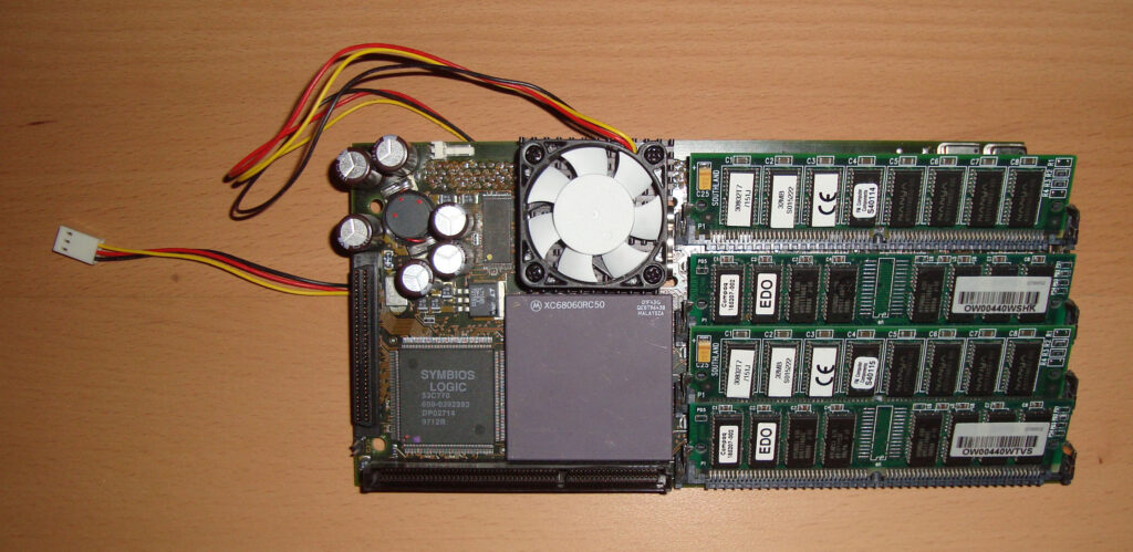
Phase 5 CyberStormPPC 233Mhz PPC / 50Mhz 68060
This was a top of the line Phase 5 turbo board that I got when I purchased an Amiga 4000D second hand in 2007. This was the top model from Phase 5 that had a 233Mhz PPC chip and a 68060 68k CPU. I had a CVPPC graphics card for it and was running SCSI with a 10k HDD that sounded like a jet once spun up. It was a fast setup but was highly complex in setting up. It was also noisy and hot running. I remember I spent a few days trying to get it going before being successful. I think I paid 400 euros for the complete system.
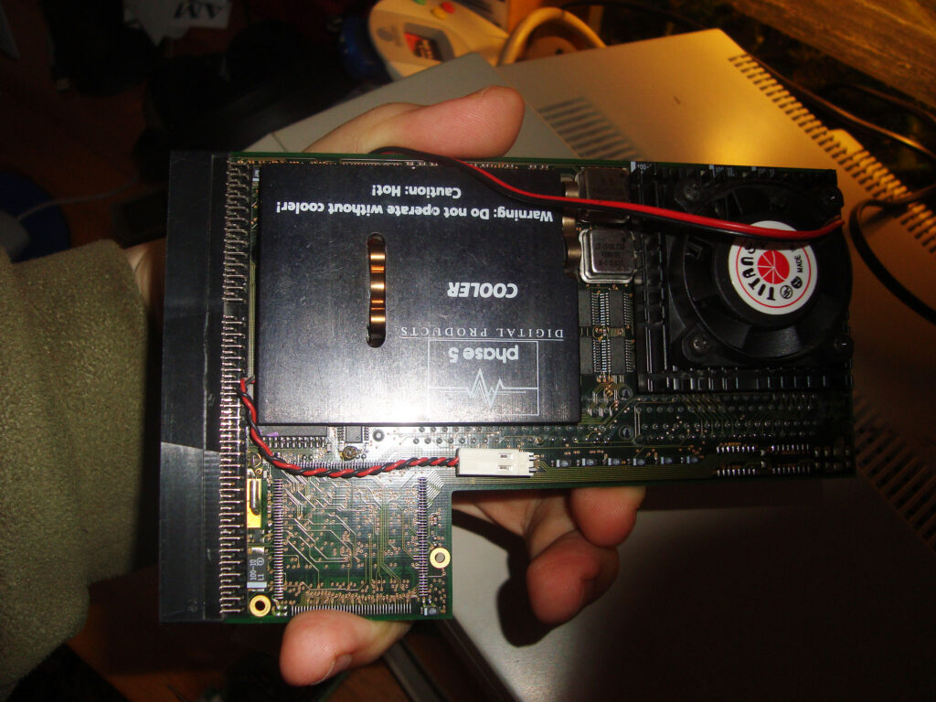
Phase 5 BlizzardPPC 200Mhz PPC / 25Mhz 68040
Here is another Phase 5 turbo card, it is the Phase 5 BlizzardPPC, I remember that it had a 68040 68k CPU and a PPC clocked at 200Mhz (I think). I have forgotten where I got this card from, I guess it was in a bundle, possibly with an Amiga 1200 tower, I had the BlizzardVision graphics card for it too.
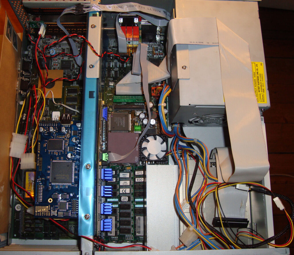
Amiga 4000D PPC setup from 2007 or so… those where the days
Here is my Amiga 4000D setup from 2007 with the CyberStormPPC installed. Not much has changed with today really, just the shape of the hardware and the amount of machines.
I got AmigaOS4 for classic PPC system and installed that on the computer above. Then I played around with some software in 68k Workbench, but no matter how I twisted and turned things I felt like I had expensive hardware that I used too little and just heated up the Amiga 4000 too much – So I sold it all!
…and now I am back (never sell stuff).
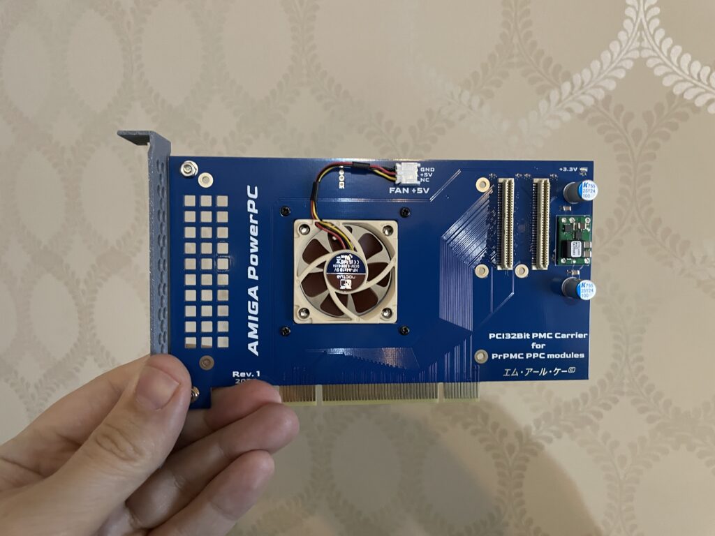
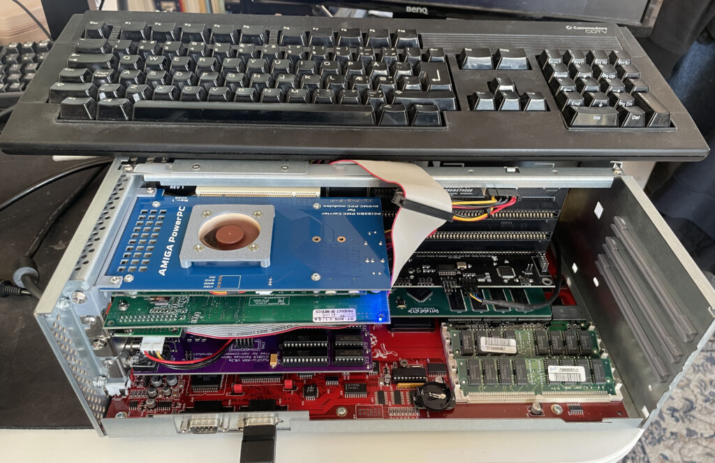
PMC PPC PCI carrier board
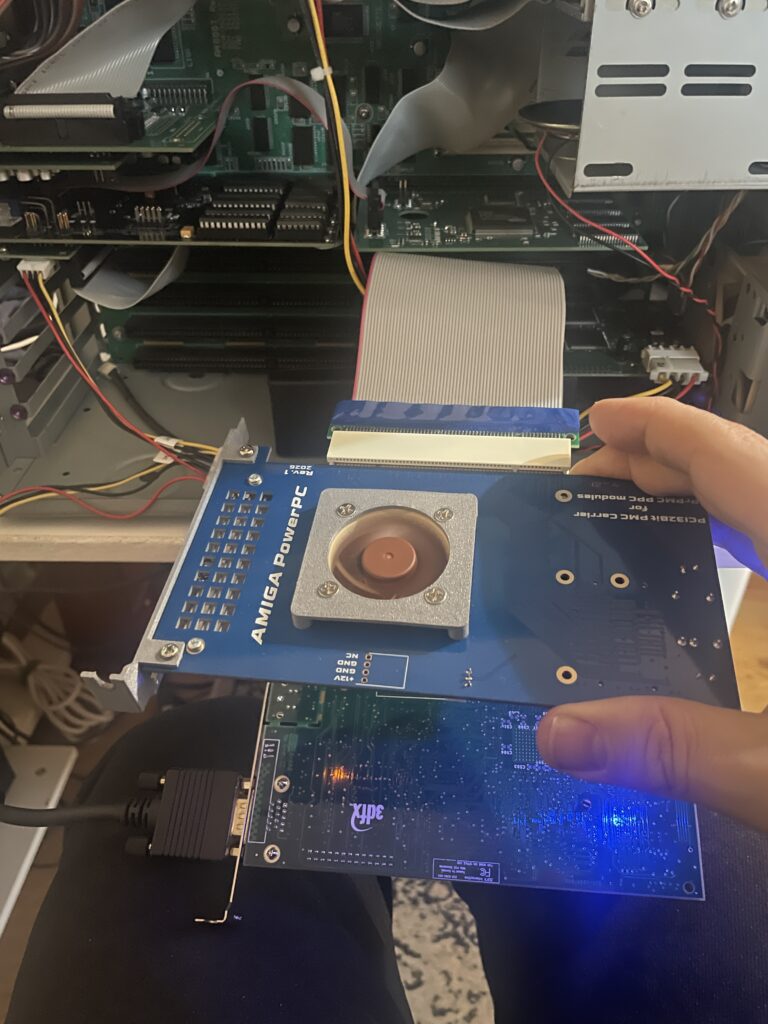
PMC PCI carrier card for PPC module
So to use the PMC PPC card above on the Amiga you have to add it to a PMC carrier that slots into a PCI slot. This version of the PMC carrier was made by a friend in the hobby that I met on a Discord channel we frequently visit. It has a small 5v 40 mm fan to cool the PPC card that sits under it.
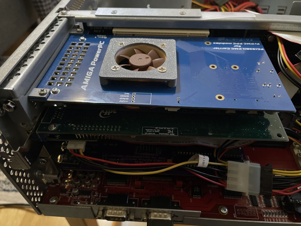
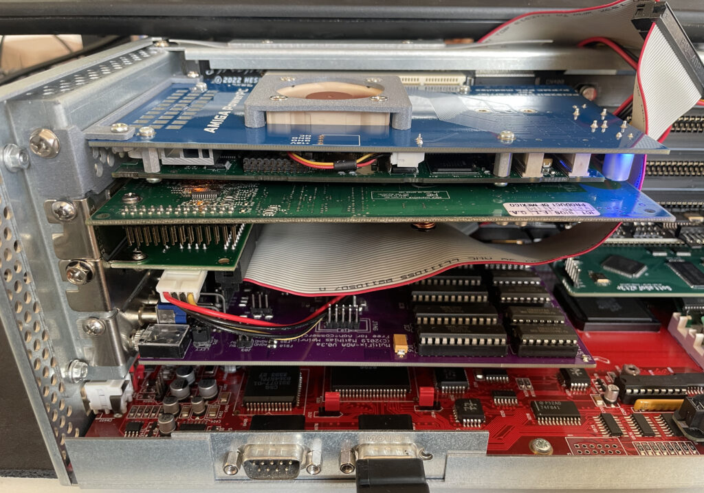
PPC card fits over the PMC carrier card perfectly
The Emerson-Motorola PrPMC8005E-1259 PPC PMC card is mounted to the PMC carrier board. As you see it is a perfect fit. The 3D printed bracket has holes for ventilation.
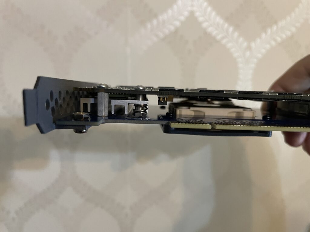
PMC carrier and PPC card sandwiched together
As you can see, the card is really slim even though its a sandwich. The CPU on the PPC card sits under the heatsink on the left side.
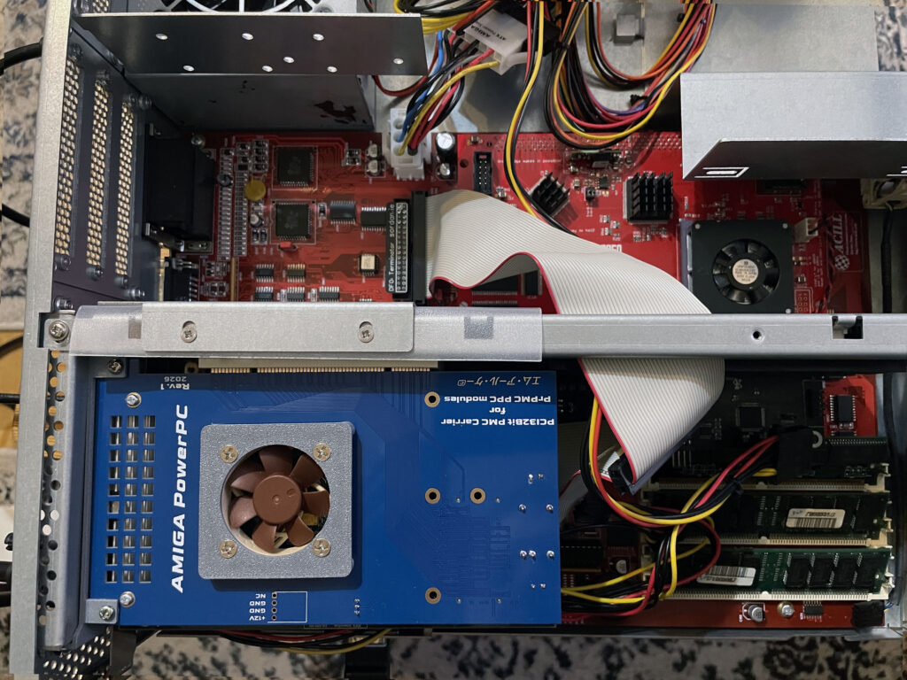
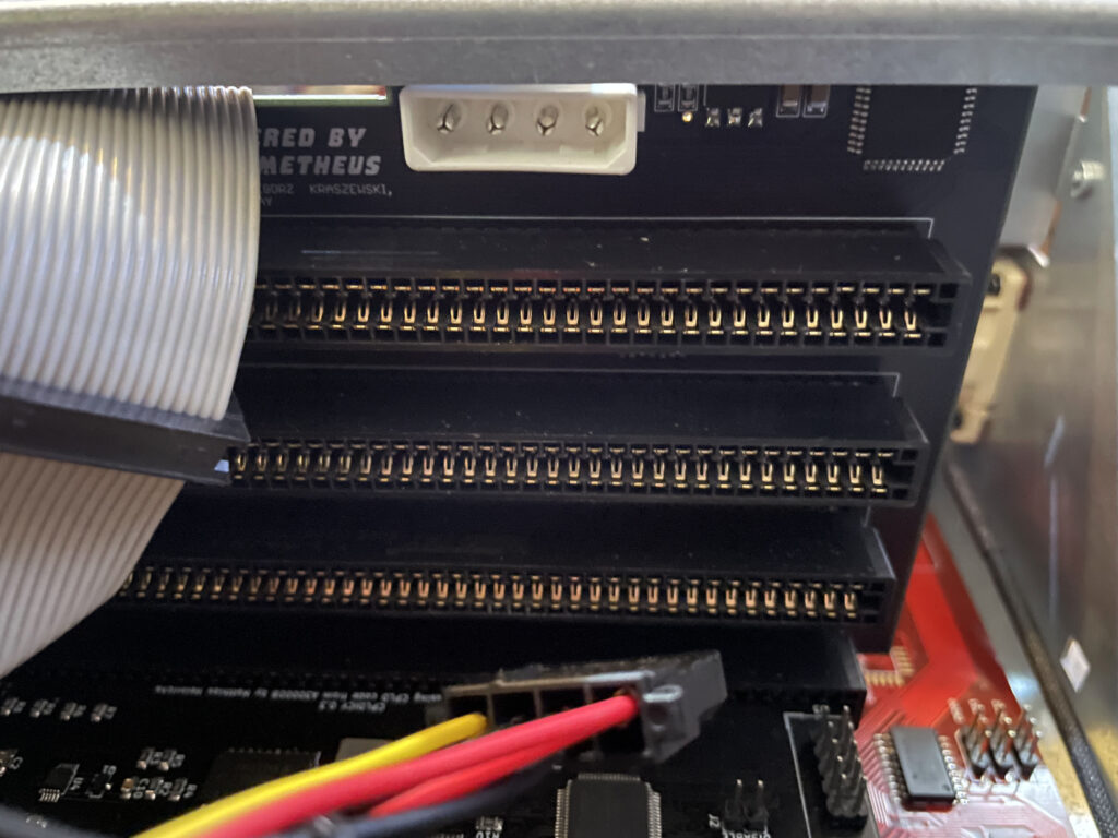
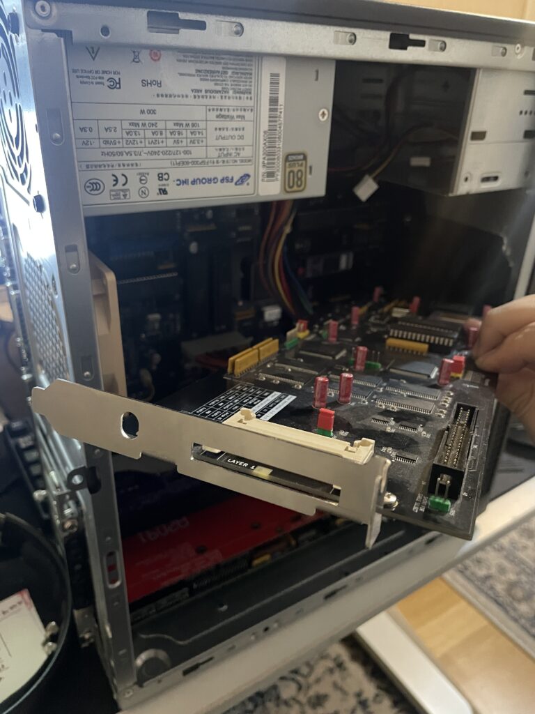
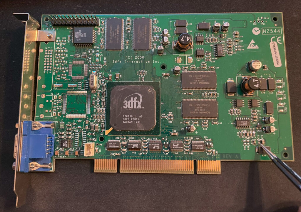
My Amiga 4000D has a Firebird PCI daughter board installed. The PPC card is inserted in the top PCI slot. The card under the PPC card is a normal PC 3DFX Voodoo 3 card, without it the PPC card wont work.
The Voodoo 3 graphics card is the AGP version, that is why the bracket is not flush with the case as there is an adaptor that converts AGP to PCI and takes up some space. Bottom slot contains a Multifix-AGA scandoubler.
My original plan was to use a 3DFX Voodoo 4 card but my Voodoo 4 failed to work in my setup in combination with the PPC card for some reason. Thus so I chosed a Voodoo 3 instead that is better supported on the Amiga.
A4000D test setup as seen from the top
Here is the setup from the top. Even with active cooling this is a really hot running setup, no joke. The 3DFX Voodoo 3 graphics card gets very hot. I wont be running long sessions with the lid on (if at all) and will possibly move the PPC/3DFX setup to a tower setup in the future to enable better cooling if possible.
To run the A4000D/PPC/Voodoo 3 setup reliably with the case closed would take some extreme cooling mods and cooling improvements to the A4000D case. Not sure how to or if I want to chop up this 350 euro replica case to enable more fans, but clearly something has to be improved if this is the way forward.
Problems with running PPC based Warp 3D software
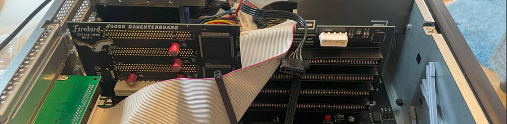
Firebird PCI Amiga daughterboard Molex power connector
As is de-rigeur when dealing with Amiga hardware something has to be weird and strange, unexplainable or simply illogical or based on an error or fault that can not be guessed by mere mortals (or it might be me who f”d up when building something in this Amiga).
In this case everything worked fine, including PPC programs, except Warp3D enabled PPC programs that crashed the system – All the time.
68k Warp3D applications worked fine. Non Warp3D PPC applications also ran fine. It was just PPC Warp3D applications that failed to run.
Can you guess how I fixed it? -By not running power to the Molex connector on the Firebird.
With the Molex connected, crashes.
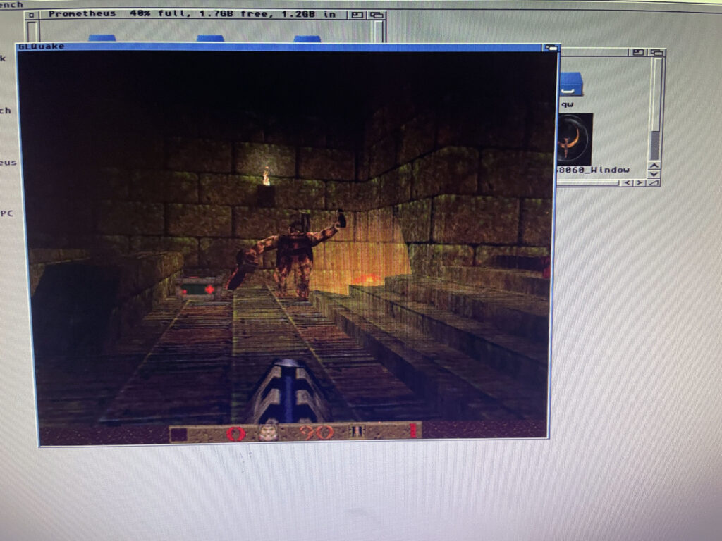
With no Molex connected to Firebird, could run PPC GLQuake all day happily. Why? -No idea.
Some demo PPC software on the Amiga
PPC was thought of as the next generation CPU for the Amiga. It was logical because both PPC and 68k was made by Motorola and 68k was not developed anymore. Motorola was not Intel which was considered Wintel and was lame and dumb.
It was a different time back then and it was much more fanatical, had they chosed ARM or Intel for the Amiga in the middle of the 90ies then probably half the user base would have left the Amiga community in disgust. Even if it could have been better.
In hindsight PPC was maybe not the right choice, but who knew it back then. What everyone wanted was the OS, Workbench, to be fully ported to PPC.
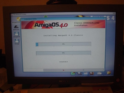
AmigaOS4 installed on an A4000D with a CyberStormPPC
That eventually happened with AmigaOS4 around 2006 for owners of a Phase 5 PPC accelerators. Using AmigaOS4 classic was nice but limited as it only supported system friendly software, understandable as it is just like AmigaOS4 for next gen hardware.
Thus for most PPC owners, they still run Workbench on 68k CPU while the PPC CPU is just sort of a co-processor that runs PPC applications launched from the 68k Workbench when needed.
But that does not mean there are no interesting PPC software to run. You wont see them here today though as I was just trying my PPC card out with some standard software such as:
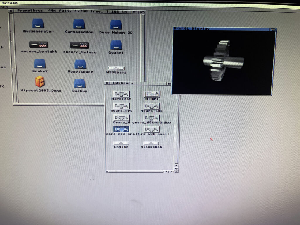
Warp3D Gears demo
Gears PPC Warp3D demo application
This is just a demo to check that Warp3D and PPC is working. Imagine the gear spinning around very smoothly. There is a 68k executable too, that is great stuff if one want to compare performance between PPC and 060.
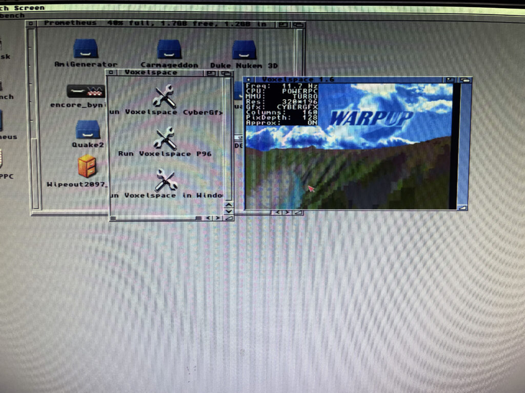
WarpUp Voxelspace
Voxelspace PPC demo application
This is another PPC demo, the Voxelspace demo where you can travel around a voxel landscape. Hit F1 to render the voxel landscape with 060 or PPC and see the impressive speed up with it running on the PPC CPU.
PPC GLQuake
GLQuake running on PPC, really fast!
Off course, the raison d’être for having hi-end Amiga systems – trying out Quake on it for 15 seconds and then doing something else.
N2630 is a great 68030 CPU card you can build yourself for the Amiga 2000 or A2000EATX project. You can find more information about the N2630 project on the website here.
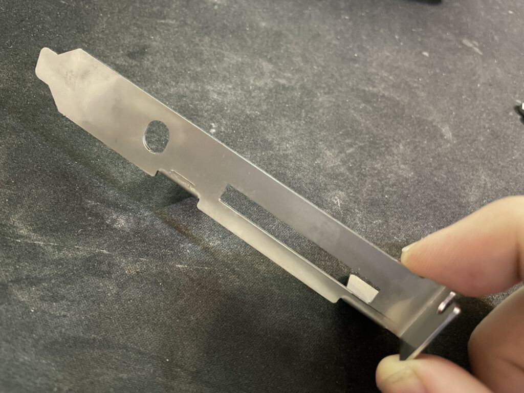
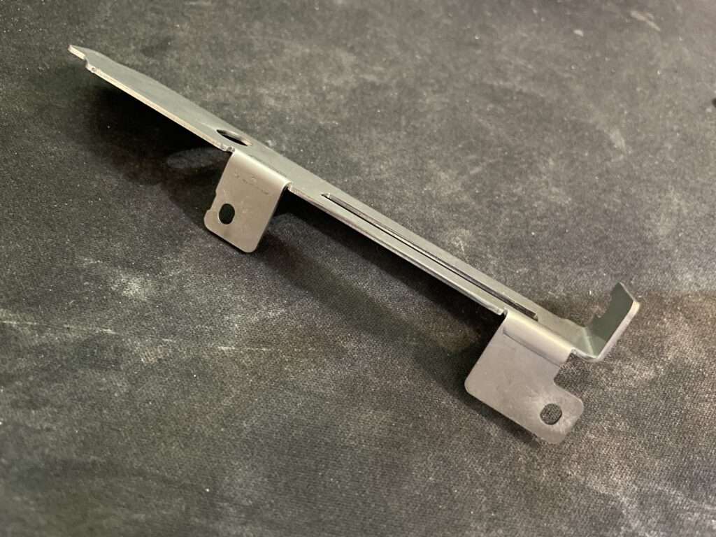
N2630 CPU card with 3D-printed bracket (that has a part broken off)
There is a model for a bracket for the N2630 that you can 3D print. I did that but it was too flimsy and eventually broke in two pieces.
I was planning on ordering a 3D metal print of the bracket from JLC but heard of arymanx on Amibay who had made a small batch of metal brackets for the CPU card. In this hobby, you have to act fast, or the chance might never come up again so in less than a week a shiny metal N2630 Amiga 030 CPU card bracket arrived to me from UK.
If you are interested in a metal bracket for the N2630 too, feel free to contact arymanx directly about it on AmiBay.
Another view of the N2630 metal bracket.
Its just a bracket, but is a great reminder of that it is the small details that makes a DIY build great.
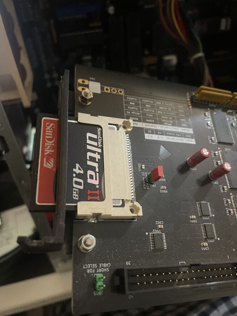
Metal bracket mounted on to the N2630, my A2000EATX is in the background.
I mounted the bracket to the N2630 with two screws and nuts. The nuts got a drop of blue Loctite to hold them secure. Fitment was excellent.
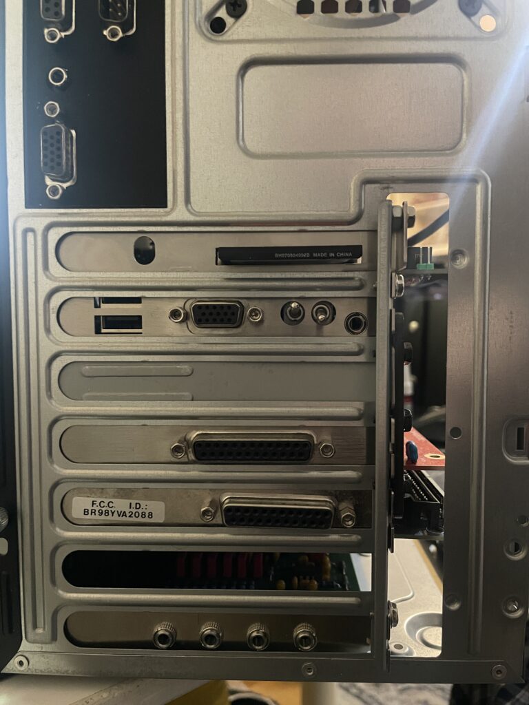
Back of my A2000EATX. One slot left for a NIC.
Not only does it hold the card better in the case it also looks better.
Pay no attention to the nut wedged between bracket and case. The CPU slot I used when building my A2000EATX motherboard was taller than a regular CPU slot used on the Amiga 2000 making the CPU card sit further out from the motherboard.
Amiga 4000D setup for PCI card installation and test run
Here is my Amiga 4000D with PCI slots. It has an Firebird daughterboard that has PCI slots, Zorro slots and one video slot. More information about the Firebird PCI boards here.
Firebird PCI daughter board for Amiga 4000D
This is an older picture of my Firebird PCI daughterboard with no cards mounted to it to get a better look at it. This was before it was fully built, that is why it only has one PCI slot.
I tried PCI on the Amiga years ago on my A1200 with a Mediator A1200LT – I was not sold on the concept as I felt the performance was lacking. Since then I wanted to give PCI on the Amiga a fair chance again and so I had to get the Firebird to try out PCI on a big box Amiga properly!
3DFX Voodoo4 PCI
Here is a 3DFX Voodoo 4 PCI graphics cad I got years ago, back when they sold for a reasonable sum. It has spent close to 15 years in storage. Along the way it got a capacitor knocked off (that I am pointing on). I replaced the capacitor, added a heatsink and fan to it and hoped that it would still work.
Amiga 4000D with PCI cards, Zorro cards and a video slot card
Here is a closeup of the Amiga 4000D with the Firebird PCI board holding the Voodoo4 PCI card and a PMC carrier holding a PPC card. I will make a separate post about the PPC card in the top slot in the future. The other cards you see is a purple Multifix-AGA, GottaGoFaZt3r and a CPLDICY.
Testing Voodoo 4 PCI RTG output in Workbench with HippoPlayer
…aaaaand surprise, the 3DFX Voodoo4 PCI graphics card worked!! Installation went really smooth even if it was not a simple point and click installation.
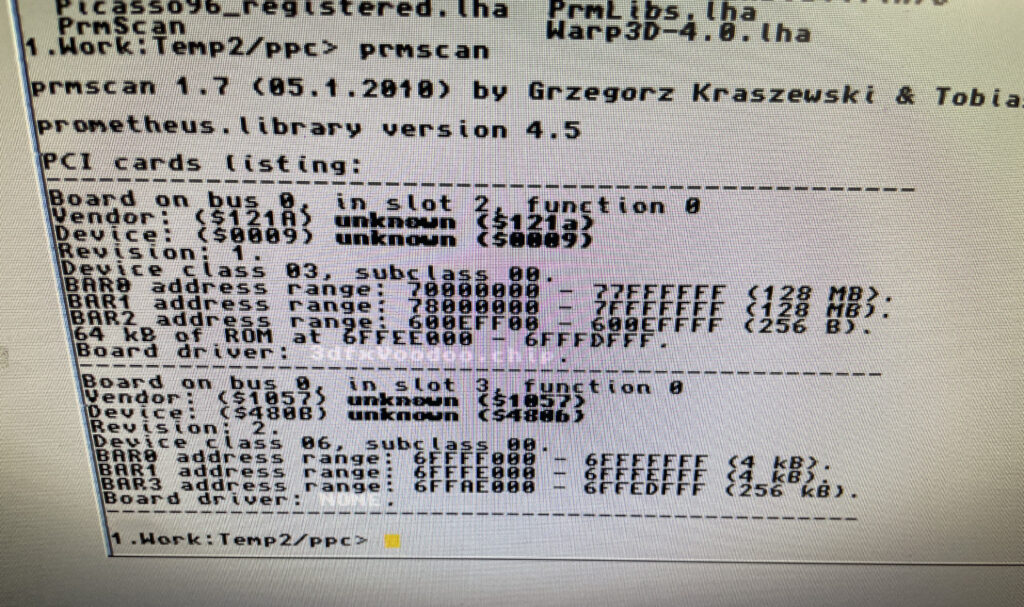
Looking at the cards listed on the PCI bus
There is only so much time on the weekend so I ran out of time installing the PPC card, hopefully I will look into it next time. I will also need to set up an automatic switcher between RTG and scandoubled output. As usual, you are never done in this hobby….
A4000TX with PLCC sockets desoldered and custom chipset removed
The A4000TX in the picture above was one of the first Amiga hardware projects I built. I was clearly way over my head when I took the bold decision to build it with so little prior soldering experience. I got it working in the end – It was a great experience in patience finding the small errors I made before I got it going.
And then I proceeded to build a second A4000TX. The second A4000TX I built was arguable a better build with the custom chipset directly soldered to the PCB, components more neatly soldered and having no 030 CPU soldered to the motherboard. But I had a lot of fun building them both and the learning experience was signficant!
As most beginners chose to do, I built my first A4000TX with SMD PLCC sockets for all PLCC chips. I made the decision to cut off the inner sqare of the PLCC sockets to make them easier to solder. Since then, soldering PLCC sockets with the inner square left is something that pose no challenge for me anymore. So the thought of replacing the flimsy sockets with high quality full 3M sockets has lived rent free in my head for a long time, as has the thought of cleaning up the build a little here and there.
Anyway, I desoldered the PLCC sockets today with a hot air station, then I cleaned up the pads and resoldered some parts that was sloppily soldered. While investigating ways of desoldering the PLCC sockets I got the suggestion to just solder the chips directly to the motherboard. On a second thought, I decided that is the way to go forward as it makes for a more stable setup, better looking hardware and cooler running chips.
Besides, I already have a spare ReA1200 I purchased from another builder with full sockets if I want to test most PLCC chips.
My Amiga Workbench 3.1 installation running DOpus 5.91 Magellan II
I mostly log my Amiga hardware activities on this blog, but I thought it would be interesting taking a look at how I set up Workbench 3.1 for my Amiga 4000D.
I prefer to install Workbench from scratch on my Amiga computers because I think the prebuilt Workbench installations you can find here and there online are configured so different than what I am used to.
While I have moved on to Workbench 3.2 on my main system I still prefer to have an older Workbench 3.1 system running and tweaked the way things looked like back in 1997.
So lets go through my wild WB 3.1 AmigaOS installation “1997 edition” that I recently set up in WinUAE for my A4000D.
Magic Workbench icons
MagicWorkbench 2 was the second Amiga Icon replacement of MWB and much better looking than the first
Back in 1997 you where either running MWB2, NewIcons or the original Commodore Amiga icon set. I prefer MWB2 because it is a beautiful icon set with a lots of icons to download on AmiNet.
Off course this is Amiga, land of drama, conflicts and useless legal battles no matter we talk about peoples egos or the type of icons people prefer – Who remembers the MWB vs NI war from the 90ies (ketchup’n’mustard-look), predating the PowerUP vs WarpOS war a year or two IIRC?
New Icons was fine but I think the design of Magic Workbench icons is just more professional and better, even the third party Magic Workbench icons are generally better looking and faster loading than NI since they are only using 8 colors.
MWB2 drawer icons in my Work: partition
What I like with Magic Workbench is that there is a huge variety of drawers you can chose from. I tend to prefer GlowIcons these days but Magic Workbench is timelessness in icon format, take for example the HDD icon that is iconic Amiga. How would MWB3 have looked liked if it was made? Magic Workbench icons in 64 colors? What could have been – c’est la vie…
Directory Opus 5
A Directory Opus 5.91 Magellan II Lister displaying partition content
I run DOpus5 (Directory Opus 5.91 Magellan II) as a Workbench replacement. DOpus5 is a complex program to talk about. But to explain it in simple terms: I use it to primary get the same functionality you get in Windows when you use Explorer to browse around the file system. But DOpus5 is so much more than just a Windows Explorer clone for Amiga and that is also why it is such a complex program to get into on the Amiga.
Check this out:
This is the content of a drawer containing music modules in a DOpus5 Lister
I have clicked on my Data partition on the image above and dived into the folder structure. I have set it up to open Data: as a DOpus Lister in text mode.
The reason why it is setup like that is the ability to browse in and out of folders quick and easy. See that blue icon in the toolbar with a green arrow pointing up?
One click on that icon takes you up in the file hierarchy. You do not have to open up 100s of drawers (and closing them), you do all the work in one window.
I have a huge module collection with thousands of drawers containing thousands of music modules. Browsing them in DOpus5 is so much more effcient than going through folders, clicking, open and closing drawers in Workbench.
Double clicking a module file opens up HippoPlayer automatically with file types set up
The function that sold DOpus5 for me on Amiga was the ability to browse folders up and down like you do in Windows Explorer (or any file explorer in any OS). But it was also the ability to click on a filetype and automatically open a program that plays or opens the file. Such as clicking on a module file and having it open HippoPlayer and playing the module automatically.
This functionality modernizes Workbench tremendously and makes exploring a huge tree of folders and files much more efficient, like the way you are used to interact with a computer these days.
Outline fonts with Directory Opus 5
Here is another cool function in DOpus5, you can enable outlines on fonts. Makes fonts on Workbench and folders more visible on backgrounds. No need to run a separate hack for this functionality.
DOpus 5 enables button banks if the user so wish to have one.
And here is a little button bank in the bottom left corner, off course you can configure this to be text instead of icons, or configure it to hide itself, or configure it to be an icon, or configure it to be a start menu, or add it as a menu in the WB bar, or change background to be a color or pattern, you get the point.
There are tons of ways of configuring even the smallest things in DOpus 5.
This is both a strength and a weakness. As a reviewer said in his conclusion in an Amiga mag from 1996 “It is very powerful, but I dont have the time to invest learning DOpus5“.
Listers can look like regular Drawers in Directory Opus 5
Just to show an example of how you can confugure DOpus5, I chose to display my Work: partition as a regular partition in icon mode to the left. But I have configured my Data partition to be displayed in a Lister as text only on the right as it contains only data files.
Amateur attempt at pitching DOpusMagellan for Amiga
There are tons of functionality in DOpus5 and I think the problem Directory Opus had BITD was that the authors crammed all possible features and functionality into the program and enabled it as default when you installed it.
I think what they were going for was for the user to go absolute bonkers and excited over all the awesome functionality they managed to add to DOpus. Not expecting users to feel somewhat lost in all menus, options, functionality and occasional bizarre configuration logic.
I spent a week playing around with DOpus5 in the evenings before i got it configured to where I wanted it to be (almost) and when I reached that point it was a very satisfying Workbench experience.
But no doubt, this is a product of its time and it shows in the amount of time that one has to invest to get it going, to understand certain functionality, find solutions to potential problems and figuring out logic behind some configuration options or even get used to non-orthodox ways of handling stuff – such as selecting files and dragging them to another lister.
My suggestion is to disable all functionality that is not needed, the amount of things that can be configured is wild. For example, if you ever has tried a standard installation of DOpus5, you can see that I removed the buttons in the lister that I will never use (such as changing file attributes). That small change makes a huge change in user friendliness.
I also do not need a text button bank with every weird file operation thinkable. In every possible color combination. With secondary function if you click with right mouse button.
Also, it has to be said, that yin-yang symbol for the parent folder button in the Lister toolbar was stupid. Who came up with that idea for that icon must have been responsible for most of the UX in DOpus5, get ready for a crazy ride back to 1997 when bad UX was considered good -because it was not as it was on Windows- if you are brave enough to take the leap.
I mean, if the button is made to go up one level in the file hierarchy, i.e. “parent”, why not just have an arrow pointing up?!
Microknight – System font
Microknight is a great classic Amiga font
Lets talk about the font I am using for CLI and the icons on Workbench. The font is called Microknight. To be honest I do not remember where I found it, but IIRC you can find it somewhere on Aminet in some package, I think it is demo scene related, you just have to Google it.
Microknight is a classic Amiga font with just the right look. Works great in hi-res but also in hi-res laced. I have used it since 1997, will probably use it in 2037!
I use XEN as drawer icons just to get icons sorted more compact with outline enabled. Otherwise there would be huge space between them.
Statram
Statram with the MWB2 icon for RAM:
I found Statram on a BBS in 1998 and really liked it. It is a RAM disk that survives resets. Statram grows with the amount of files that is added to it (SD0:). It is perfect to extract files to. And it is also perfect these days when we can have 256 MB+ without paying through the nose in our top of the line hi end Amiga computers. Some even has 1 GB.
TitleShadow
TitleShadow adds a tiny shadow to the titles on drawer window titles or partition titles.
TitleShadow is a cool Workbench hack that I found this year, wonder why I never found out about it before.
TitleShadow adds a shadow to the title of the drawer windows. Highly recommended. Wish it could be used on the icon text too.
Birdie 2000
Birdie 2000 enables images in Workbench borders for some wild looks.
Birdie 2000 is one of my all time favorite Amiga Workbench hacks/enhancements. It is much more than just a rotozooming image of a cool parrot. It is actually used to place an image file in the border of Workbench drawers (try clicking on the executable).
I remember when it came out, it took the Amiga community -including myself- by storm, suddenly everyone started to experiment with wild setups, from the most extreme to the more subtle – nothing was forbidden and everything had to be proved by taking a snapshot and uploading to AmiNET or shared on IRC.
In my Amiga Workbench setup I have a rather wild setup with many colors, this is supposed to be 1997 after all, but that is no reason not to go for something more subtle such as a light gradient as you can define two colors that creates a gradient from color A to color B.
The possibilities with Birdie for a highly personalized Workbench are endless and I had a ton of fun playing around with it BITD (and today) – I even ran it on my A1200 with AGA and 030 in 128 colors back in 1997!
This was hi end 3D rendered graphics and cool in 1995!
I remember that I emailed the author of Birdie back in late 90ies asking where he found the background image he used on the demo image of Birdie uploaded to AmiNET BITD. He did not have it or knew where he got it. But just recently, 2-3 years ago, I found the exact image as seen above, it is as wild as some Birdie enabled Workbench setups looked like – funny thing is I dont remember where I found it, what comes around goes around…
Birde is configured through CLI but there is a third party GUI for it, although from a usability perspective BirdiePrefs was highly confusing getting used to the first couple of times i used it. BirdiePrefs and Birdie should have been added to Workbench 3.2, make it happen in 3.3!
VisualPrefs
VisualPrefs is an awesome WB hack that lets you change the look of borders and other GUI parts of Amiga Workbench.
If you wonder where the look of the window gadgets comes from on the pictures it is from changing them in VisualPrefs.
I mainly use VisualPrefs to get chunkier buttons for drawer windows and to make the UI proportionally better. There are also some nice options to generally make the UI look better. I set it up to the same style I always run when installing it, XEN gadgets, with thicker title bars and proportional arrows. Exactly as how it looks like in the picture above.
Depending on what screenmode the Amiga is running the gadgets of a drawer can look disproportional. With VisualPrefs it is possible to change proportions of gadgets to make them look better depending on what screenmode you use.
The possibilities in VisualPrefs is huge, but as I said above, I tend to go for the same kind of setup all the time. Which is a shame since there is a ton of functionality and even possibilities of building themes and adding bitmaps to the workbench title bar in it. Maybe some day…
ClickToFront
This is placed in my WBStartup folder to make programs and drawers pop to the front by double clicking the upper border of a window.
KingCon and Amiga shell setup
KingCon is installed to enable tab completion of filenames. I think I will change to CSH as KingCon did not click with me. I have also set up CLI to have a black background with white text.
MUI, P96, AHI and all the rest…
Off course, no Amiga Workbench 3.1 installation is complete without the essential add-ons such as MUI, Picasso96, AHI, data types, a bunch of background images to keep Workbench fresh and that odd app and hack here and there…
I am also running a file requester replacement that I have forgotten how I installed. IIRC it was a replacement library. Main reason the swap file requester was to get directories to list before files in the file requester.
Partition setup
I also want to point out that I always install Workbench to a partition called Workbench (DH0:). I always create a Work partition (DH1:) that contains all programs. If I am installing on to a larger harddrive I also create a Data partition (DH2:) for files such as modules.
Typically I do not install any general use programs to the Workbench partition as that should contain the operating system and files relevant for Workbench only (such as Picasso96, MUI and so on). For example, I do not install Ibrowse to that partition as Ibrowse goes into the Net drawer in Work. Neither Deluxe Paint as that goes into the Graphics drawer in Work.
Some of the ready installations of Workbench floating around the net has a weird missmatch of installed software in different locations all around partitions with less structure than I am used to. It is not bad, just an example of the benefits and freedom of installing Workbench from scratch – You can get it exactly as you want it!
Conclusion
Using an Amiga running a Workbench that is tuned to your preferences is a great pleasure to use.
Apocalypse PrPMC8005E-1259 450 MHz PPC card waiting for its PCI carrier to make it work on a PCI Amiga Z3 system.
Don’t know why or how, but somehow I am back on the classic 68k PPC hype train! Enjoy watching me rip my hair off my head trying to get this PPC board going in my A4000 in the future!
A set of custom chips from an Amiga 1200 resting in a plate of IPA
Bought a rotten non working Amiga 1200 motherboard recently and spent the evening desoldering and cleaning up the Amiga custom chips. TBH I was only after the Alice chip… hope it works!
Update on the Amiga custom chips: 2026-02-01
Amazingly, all chips was confirmed working! Especially considering the motherbaord that I desoldered the chips from looked like this (warning):
A thick layer of dirt covering the A1200 motherboard. I especially like the unmatched Kickstart chips!
This is how I tested the Amiga custom chipset, I have an ReAmiga 1200 with sockets for the custom chips so I could just swap the chips on it and give it a go in Diagrom. I bought this Amiga 1200 motherboard built by someone else. I do not recommend building it with sockets, but for testing purposes it is fine.