Find the missing chip on the ZZ9000AX Amiga sound card
I wrote about the troubles I had with the ZZ9000AX soundcard for the ZZ9000 graphics board in a post a year ago. No matter what I tried I got a horrible distorted sound from Paula if Paula output was routed through the ZZ9000AX. That was just half the story, the other half was the insane bus noise the card picked up. I was not alone with this problem as I heard quite a few who had the same disappointed stories to tell about their ZZ9000AX Amiga sound cards. One chap I know called the card “an utterly terrible piece of sh*t hardware“.
An intense discussion with the creator of this card followed where it was concluded that the problem could not be confirmed, a pointer to the schematics of the card was offered – An electronics enginering degree was however not offered. Maybe then I could have found the error myself.
Patience rewards those who wait, that is something every Amiga user knows about, it is just a matter of time before Amiga will take over the computers of the world and become the no.1 computer again.. oh wait its not 1998 anymore back to the ZZ9000AX and 2025…
Good bye…
So I was hanging out in a Discord and noticed rumors about the ZZ9000AX now performing fine by doing a simple hardware modification to it. Apparently, removing the chip U4 from the ZZ9000AX would fix the insane sh*t quality (mildly speaking) output from the card. After further investigations it was brought up that this groundbreaking news was communicated on an IRC channel (yes, it is 2025) for the Amiga community to pick up on (why not post it on usegroups next time?).
I could barely keep my hand off my soldering iron – In 5 minutes the chip was removed from my ZZ9000AX never to be seen again. If the card failed in the process I could always retire it in the round archive (meaning, in the garbage where I had been tempted to put the card to rest for more than a year).
Would it work or not!?!?!
In the middle of a brutal 90 min Amiga module testing session with my A4000TX running ZZ9000/ZZ9000AX
IT WORKS!!!!!!! The distortion and heavy background noise is gone.
But I can still hear some bus noise in the background when opening drawers, in comparison with how it was before, this is something I can live with.
Alicia is an Amiga 1200 clone in the popular Mini-ITX form factor. It is a nice DIY project you can buy as a semi built PCB. As I had previously built a couple of Denise A500+ clones, deciding to build the Alicia 1200 was a no-brainer and I think I was not alone in that thought as the interest around it has been great! Read more about the project here.
I remember fondly when the Mini-ITX form factor was released to the public around the new millennium. It was a really exciting time in PC hardware and watching the new tiny form factor it grow and become an established platform has been a pleasure to see and experience since I have been on the Mini-ITX train many times since then.
But to be able to see, build and own Amiga systems in this small form factor with real Amiga chips is the icing on the cake – Amazing!
Denise, Alicias little Amiga sister
Denise A500+ ITX with TF536, Denise NIC, Mini Graka, Indivision ECS v3
I have not written a lot about Denise, the A500+ clone, here on my blog even though I have wanted to do that for some time.
I “blame” the beginnings of my interest in this “wallet busting” hobby on this specific project, YOLO. So expect a better post later sometimes. I remember watching plenty of YouTube clips of doing SMD soldering with a soldering iron 5 years ago and asking myself, “can I really do it?”, then I ordered a Denise board and a package from Digikey. Unpacking the first 0805 capacitor, I questioned what I had gotten myself into back then.
Anyway, I think it could be interesting to show off my Denise build before moving on to the Alicia 1200.
The Denise is an Amiga 500+ clone in Mini-ITX form factor, it has all the regular chips the A500+ has and also two “dumb” (as in no Buster) Zorro 2 slots. The PCB is jam packed but everything is beautifully laid out on the board.
Point I wanted to make was that this has been a very stable Amiga and it is awesome to have an Amiga with a small graphics board, scandoubler, NIC and 030/HDD in a standardized small form factor – That it is Mini-ITX is just icing on the cake.
To think this kind of hardware was A2000 territory yesterday is crazy. Anyway, let’s move on to the Alicia Amiga 1200 AGA clone…
Approaching the Alicia 1200 Amiga 1200 clone build, what have I gotten myself into?!
Alicia 1200 is a small PCB and most of the stuff for the build fits in this small box!
Alicia 1200 is a kit, so one have to build it oneself. I have built a few Amiga kits myself as stated above so I did not expect any problem with the Alicia build. I usually build my projects from scratch, but in this case it has all the passives and common chips mounted. This saved a ton of time.
Lets talk PLCC sockets and chips
I decided to build my Alicia without PLCC sockets. I have a technique that works really well for soldering PLCC sockets without removing the inner part of the socket. In my experience soldering PLCC chips directly to the PCB makes for a more secure connection and eliminates any potential contact issue. I feel hot chips such as Paula, Lisa and Alice runs cooler when soldered directly to the PCB. I do have a few Amiga motherboards with full PLCC sockets for testing purposes.
Soldering the PLCC chips might be difficult if you are not used to doing them. I solder the PLCC chips with a relatively large hoof tip. Not saying the hoof tip is the definitive success factor. My success is probably from doing a LOT of PLCC chip soldering and getting used to a specific technique.
Difficult to find parts aka “ahh shieet here we go again…”
Most parts for the Alicia 1200 can be taken from an Amiga 1200 or can be found on Ebay, Amibay or from the “usual” places.
You will need the full Amiga 1200 chipset, including Motorola 68020, Budgie and A1200 Gayle. You will need an ADV101 or VP101 but you wont need the keyboard MPU. Memory can be taken from an Amiga 1200 too (but pay attention, some revisions come with incompatible memory that physically won’t fit). If you want to run the RTC you need a clock chip.
A 23 pin video connector is not needed and in fact can not be used, instead Alicia uses a regular VGA socket, so you have to make your own RGB cable if you plan to use it with SCART. You will need a PCMCIA connector, but that can also be take from an A1200 motherboard (hot air is your friend).
Everything else can be ordered from Mouser or Digikey.
So lets get the soldering iron warm…
Budgie and Motorola 68020 are done, drag soldering is your friend!
The first parts I soldered was the Budgie and the Motorola 020 CPU, they are both surface mounted chips and where desoldered from an Amiga 1200 motherboard. I actually did not know if they worked or not, but as they are mounted in a good position on the motherboard I could always desolder them and replace them if they failed to work.
Lets add some memory to the Alicia 1200
SOJ40 memory is soldered to the Alicia 1200 motherboard, flux is your friend in this case
You may have built a ReAmiga 1200 and struggled with the memory, I have. It is difficult to do a good job when the chips sit so tight together. I am not a fan of using hot air to solder them. Thankfully on the Alicia 1200 the memory chips are generously spaced leaving plenty of space for my preferred hoof tip technique making this task very enjoyable. This shows in the clean result.
Lets add some PLCC chips
First PLCC chip, Gayle, is soldered to the PCB, only six more to do!
Now its time for some PLCC chips. I have nailed the technique for soldering PLCC chips. But the challenge is getting them aligned correct on the solder pads so the joints form a straight line. I got successful with the first chip at the top left, Gayle. If you fail to align the chip it will still work but may look a bit off. Depending on your level of OCD this might be totally acceptable though.
All Amiga chips are now soldered to the board. But there are still plenty to do.
Here are all the PLCC chips soldered to the Alicia 1200 PCB. I think this was around 4 hours of work in total. No idea if it works and no way of testing it yet. Let’s hope it works.
And lets add some ports and connectors
Almost ready for the first test run, what if it does not work!
I am not alone when I say there is an universal curse around BOM orders. It is an unofficial rule more than an exception that it is derigeur to miss to order some small part or important part. In this case, it was a small chip on the bottom of the PCB and the ATX power socket.
First test run of Alicia 1200 A1200 clone
It is difficult to see, but there is a blue Indivision MK3 mounted on the Alice chip
Once I got the missing parts I was eager to try Alicia 1200 out and see if it was working. And it was here I stumbled upon a problem, I did not have a suitable screen or RGB-SCART cable to test it. I thought I could use a 23 pin to VGA converter and hook up my old RGB-SCART cable with a 23 pin connector, but it did not work.
Just to verity that it worked I opted to do a testrun with a temp solution: using my Indivision MK3 that I have in my Amiga 1200 so I could get HDMI output.
Update: I have since built a VGA to SCART cable according to the instructions in the manual and I recommend everyone to do that to test that the port is working.
And it works!!
Testing AGA chipset with DiagRom
DiagROM boots and all tests checked out fine! The image above does not do justice to the image quality of the Indivision MK3, I was almost ready to fork out cash for a second one! This is a beautiful hardware combo if you want AGA only.
Sound played fine on the Alicia 1200 when testing channels in DiagROM. I think the sound circuit is the same on the Alicia 1200 as on the Denise as i recognice a few of the parts on the motherboard here.
I would descibe the sound on the Denise as slightly tinny, metallic or a bit more clean than a regular Amiga 500 or Amiga 1200, it is an interesting attribute of these motherboards and adds another dimension to the sound output of the Amiga. Cant wait to try it out with the Sound Enhancer.
Lets finalize the Alicia 1200 Amiga A1200 clone build
Alicia 1200 fully built!
Once Alicia 1200 was fully tested I could go ahead and add the final connectors including the PCMCIA slot (that I cut down to make it shorter since it sticks out a lot).
So let’s end this post with some features that Alicia 1200 has that a genuine Amiga 1200 does not have. First it has a real time clock. Then it has a video slot on top left side. There are no devices to connect here today, but there are rumors of scandoublers and other exciting stuff. Lets see what the future holds. I have suggested a 3DFX card numerous times lol.
The Alicia 1200 Tornado slot CPU slot adapter.
The larger slot is the Tornado slot, as you can see on the image above it is converted into the Amiga 1200 slot. Hopefully someone will release a direct mount CPU card for the Alicia 1200, if not, we can just use the converter above and run our TF1260s or PiStorms or whatever will be available directly on that.
Next steps!
Let me follow up in the future what case I will chose and what CPU card I will use. I am leaning towards PiStorm, but the beauty of a 060 in this little system is very tempting, almost too tempting to resist. And with the way the CPU card is mounted, there is plenty of space to run a badass heatsink over the 060 unlike in an Amiga 1200… you can be sure I will follow it up here in the future!
Just finished the last bit on the AmiGUS I built this weekend. I don’t have an USB blaster so wont be able to program it yet… if it works I will build two more for my self and have two PCBs for sale.
My Alicia is ready for a test run, but I am missing two key parts, one IC I forgot to order and the ATX PSU connector. Hopefully it works because its going to be a challenge replacing some of the chips if not.
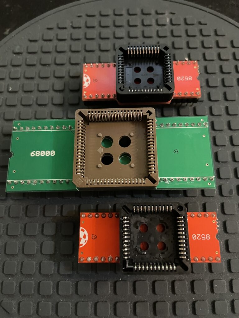
I have had these DIP to PLCC adapter kits in my stash for quite a while, today I finally gave in and built them. They are usefull if you want to use PLCC Amiga CIA chips instead of DIP CIA chips and for using an PLCC Motorola 68000 CPU instead of a more common DIP 68000.
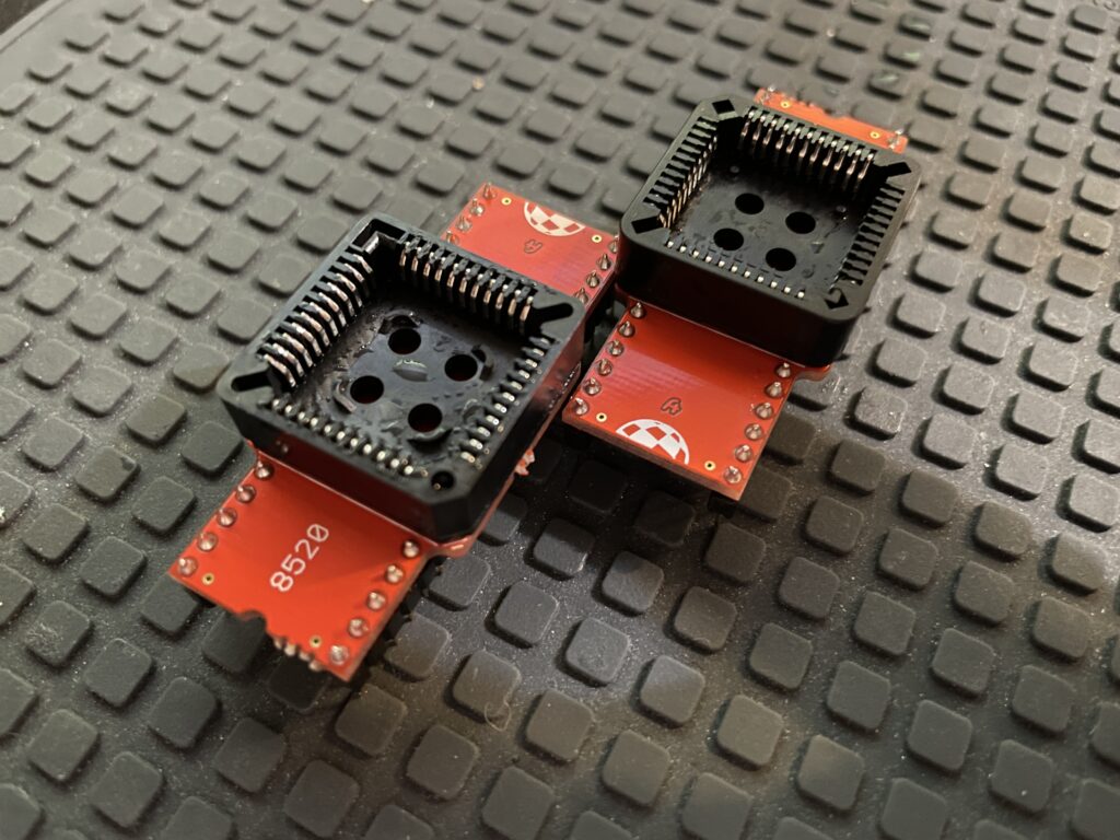
Commodore Amiga 8520 CIA PLCC to DIP adapter
These 8520 PLCC to DIP adapters has just been washed after being built.
Amiga 600, 1200 and 4000 uses PLCC 8520 CIA chips, these chips can be used on Amiga 500, 2000 and Amiga 3000 (I guess on the A1000 too) with a DIP to PLCC adapter. In my experience it is actually cheaper to get a real DIP 8520 instead of using an adapter and a PLCC CIA for Amiga computers that can use them as they are a bit more expensive on the market. But if you are like me and have a stash of 100 PLCC CIA chips then you gotta do what you gotta do (obvious joke).
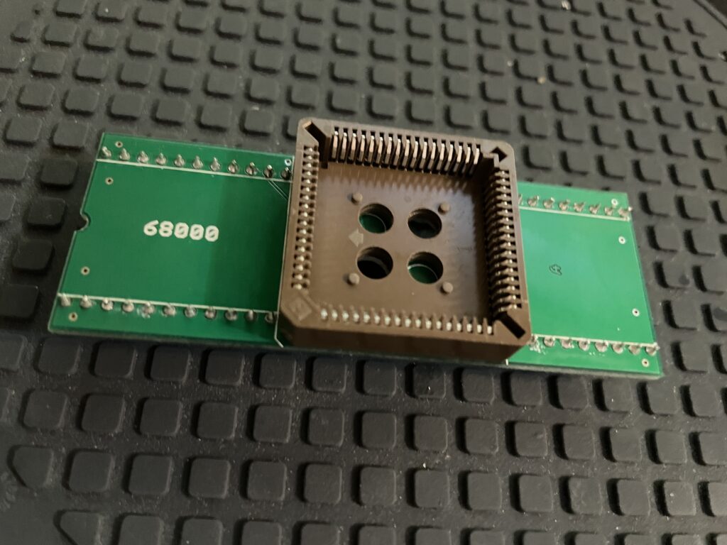
Motorola 68000 PLCC to DIP adapter
PLCC 68000 CPU is not that common but it is used in the Amiga 600 (and IIRC in the Atari ST). You can run one in an Amiga 500 and Amiga 2000 with a DIP to PLCC adapter. Why would you want to run a PLCC 68k CPU instead of the DIP Motorola 68000 CPU? No idea, but it looks cool.
Build tips for PLCC to DIP adapters
Do the pinstrip first by soldering two legs on each side only and making sure the pinstrip is straight, you can also fit the pinstrips in a socket. Then solder down all the legs.
Cut off the upper pins that will sit under the PLCC socket with a sharp cutting tool. Cut them off as close to the PCB as possible.
Then solder the PLCC socket, use flux to make sure solder does not short legs outs.
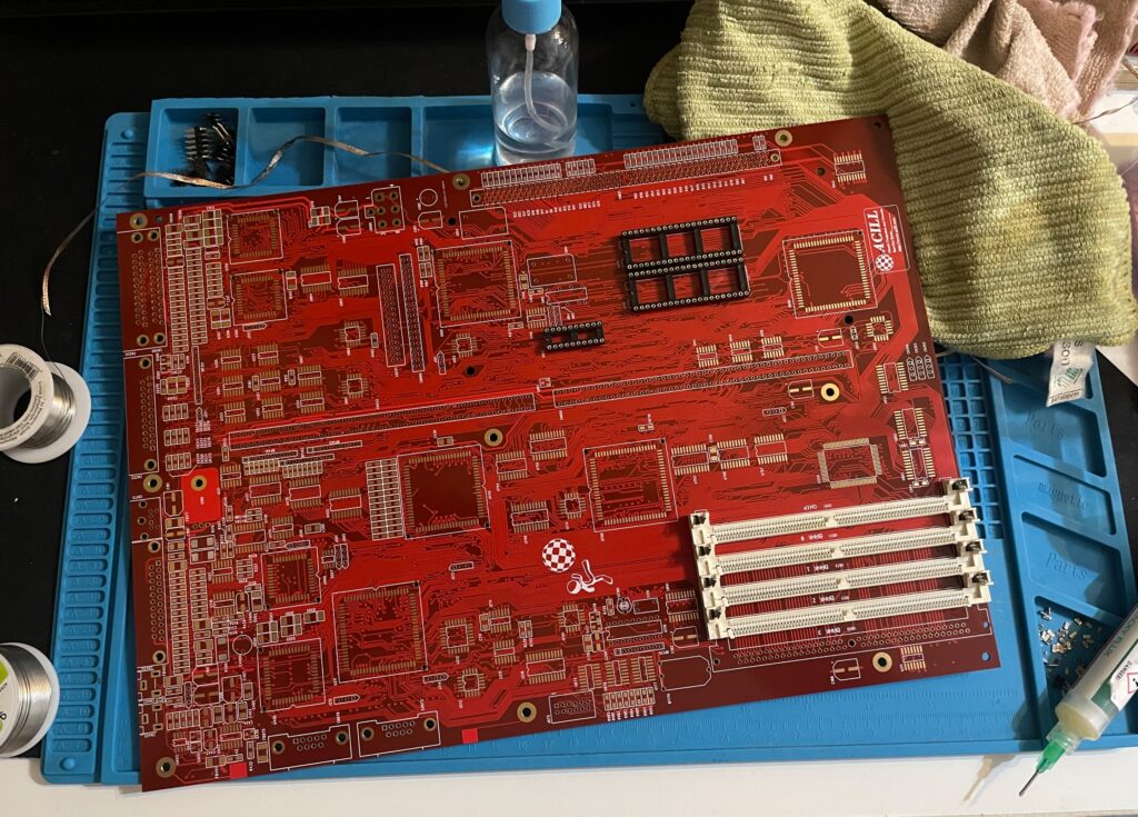
This is an A4000+ Alice PCB, it is an Amiga 4000D CR replica motherboard and it was created by the talented Hese who has made some awesome Amiga clones and hardware available to the community. If you are interested in buying an Alice A4000+ PCB, check out this thread on AmiBay (not sure you can still get one though but maybe one shows up second hand).
This was supposed to be my summer project of 2025 and I could not resist to share it on my blog even though it is not 100% finished yet. It took me about 2-2.5 months to reach this state as I was in no hurry during the summer to finish it. It is almost finished, just missing the DB slots, battery holder, two sockets and an electrolytic capacitor. Oh and all the custom chips off course, but I have a full A4000 chipset sans Buster and Ramsey…
A full socket Amiga 4000D motherboard build
The reason I did a full socket built was that I was thinking it could come in handy if I would need to test custom chips in the future. One of my A4000TX motherboards was built with sockets, but I did a bad job, cutting out the center sections from the sockets before soldering them. So I want to convert the A4000TX to soldered custom chips and have this one as my primary testing station (or primary A4000D motherboard, nothing is static in this hobby).
The other reason I did a full socket build was that there are quite a few projects around where users are looking into cloning the custom chips. Most of these solutions are using a PLCC plug that mounts in a PLCC socket, so if everything goes as it should go, perhaps we can have full custom Amiga chip clones in the near future! Woops, better sell your stash of Buster 11 while you still can get 150+ euro for them!
On schedule and rocking + two more weeks!!!!
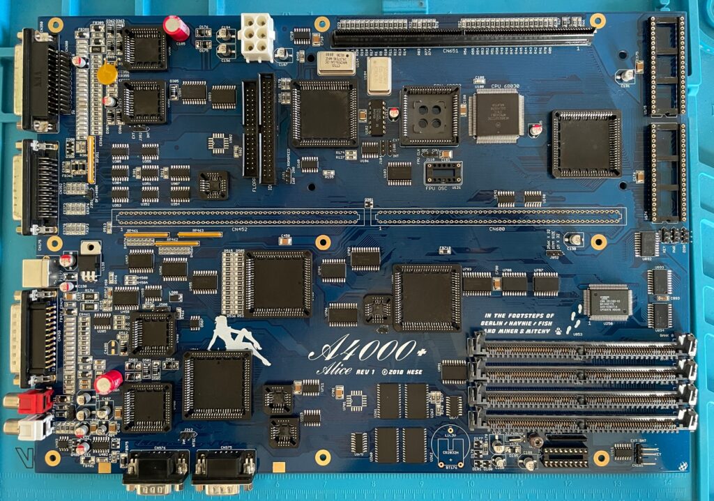
The A4000CR is an interesting motherboard as it is slightly different than previous revisions of the A4000D motherboard. There is a 030 on the PCB and the chip memory is already soldered to the PCB, thus it only has four memory slots in comparison with previous revisions of the motherboard that had 5. So if it comes without a 030 CPU board and with one less SIMM socket, there is some money to be saved, thus CR.
Once this project is fully finished, I then have a beautiful red Acill A4000D motherboard to build, perhaps my next summer project?
Can’t wait to fire up this beautiful blue Amiga 4000D motherboard in a month or two and give it a test run.
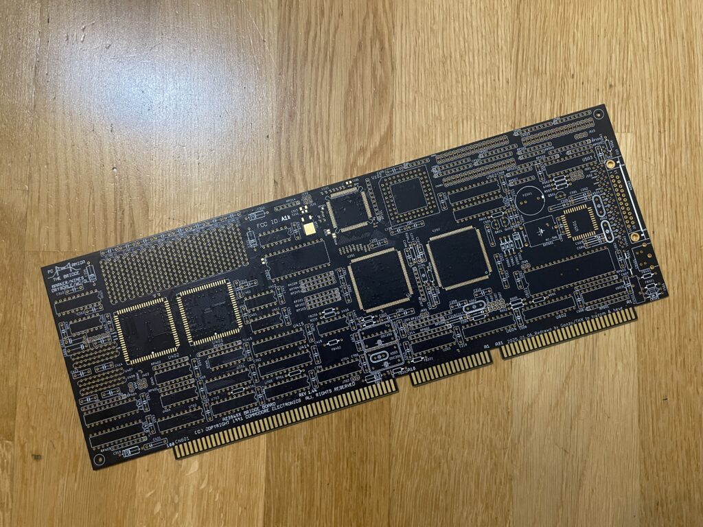
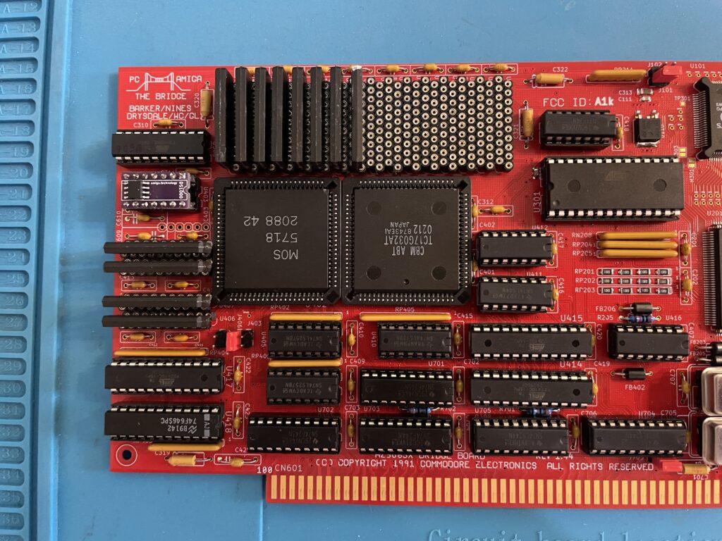
A beautiful replica of the A2386SX PC bridgeboard by Commodore.
This is an amazing replica of the Commodore A2386SX PC bridgeboard, you can find out more about the project here. There is also a discussion forum about the card on the German A1K forum (just use auto translate in your browser if you dont speak German).
Background
The A2386SX was the best PC bridgeboard Commodore made for the Amiga, it was based on a 386 CPU, could be expanded to 8 MB and enabled you to transform an Amiga in a multi CPU system that could run tasks in parallell on both CPUs, one in Amiga Workbench and the other in MS-DOS on the bridgeboard – at the same time. You could for example hop in to MS-DOS and run your programs and then multitask back to Workbench while programs where running in both environments.
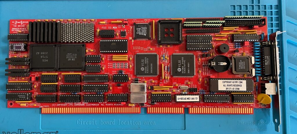
This is a beautiful replica of the A2386SX PC bridgeboard by Commodore.
I got my PCB late in Q1 after contemplating if it was even possible for me to build this card at all. Building it was not the problem. The main problem was finding all the parts and programming some of the chips. But I quickly came to realization that it was actually possible to locate almost all the parts if I pulled the trigger at the right moment since some of the rare parts this build required was disappearing fast on Ebay.
My main goal of running the card is to have access to multi channel module players such as Cubic Player and to be able to play PC modules in MS-DOS with a Sound Blaster 16. I would also like to dive into some old MS-DOS applications I used to use 30 years ago and play some old DOS game or two. But the main attraction is PC music without having to get a separate PC just for that.
Some notes on parts and building the A2386SX project
The A2386SX was an old card so it uses ZIP ram instead of SIMM modules as does the replica
There are some very rare parts required for the A2386SX bridgeboard. The rarest chips are the two socketed PLCC84 Commodore chips and the PC chipset in the middle of the card.
The Commodore chips (MOS 5718 and the chip besides it) can be taken from 2088 and 2286 Bridgeboards (they are the same), they might pop up on eBay, but consider that a miracle if they show up. I got my chips from a cheap 2088 that I bought second hand last year. Did not know what to do with that card at the time, but it was too cheap to pass up on and I am glad that I got it now.
The PC chipset should in theory be easy to find online, but so far, I have only been able to locate one of the chips. The other chip needs to be ordered in bulk from a specialist in rare chips and is costly. I thought it was possible to find an old motherboard and desolder them from there, if you find a motherboard that has them – consider that a miracle!
Then we have other obscure chips such as the floppy controller, programmable chips (that needs a special vintage programmer or someone with better skills than me in understanding how to program them with a modern device) – not really a problem to find them.
ZIP Memory can be found from obscure part specialists (remember you need two types of memory). The CPU is available on eBay, but if you want the faster 486 that is compatible with the card, good luck, as said, miracles can happen!
A difficult to find item is the capacitor networks, you can cheat and use adaptors instead. I wonder if those are needed if you wont use a floppy drive with it though.
Bracket was sourced from another enthusiast who ordered a batch. 646 was taken from my donor A3000.
Full socket build
I did a full socket build, thinking it would make it easy to error check or replace chips. And if by miracle I would build a second card I will be able to test the chips before building it.
486 CPU instead of 386 CPU
So while this is a 386 bridgeboard it uses a 486. I did some research earlier this year when I built my card, unfortunately I have forgotten the exact details, but it is possible to use a special 486 CPU on the board as they are the same physical size. I think what is most important is that the voltage level is the same as the 386 that it is supposed to use and you need to fiidle with the BIOS.
This mod works on the original Commodore A2386SX card also. This is a nobrainer for me since I grew up on 486 PCs.
Failed test run and successful test run!
So after having received more than 10+ packages containing parts for this build from around the world and a the main passives from Mouser I decided to finally build it up. How exciting!
I was really looking forwards doing the first test run after I got the programmed chips back from a friend in the hobby who could program them. But disaster happened – Bummer – The first test run failed – the card refused to run!
Most of my projects I build usually run fine on the first go, if there are any errors it is usually a bad solder joint on a surface mounted component, a dirty board or something that is missing.
In this case I knew I would never figure it out myself, especially after visually inspecting it 10 times, So I sent it off to another friend in the hobby to get it checked.
Turned out that I had used the wrong memory (I had used the memory from my donor Amiga 3000) and there was some small difference between the type of ZIP mem I used and the one that worked with the card. There was also an error in the BOM that has since been updated where bussed resistor nets where specified instead of isolated (or was it vice versa).
Once I received the card with the correct memory and resistors I did another test run and could confirm the card to be fully running!
Next steps
I probably did not realise how much work it would be to set this card up so thats why I will do it after summer. But the plan is to get MS-DOS 6.22 up and running with Windows 3.1. I will run an ISA graphics card and an ISA sound card and will also try to run the HDD off a partition on the Amiga HDD. But as it stands now the A2386SX is fully working and ready to take its place in the big box Amiga that will be its home in the future.
Would also love to build a second card, hopefully there will be an up to date model with chips replaced with CPLDs in the future!
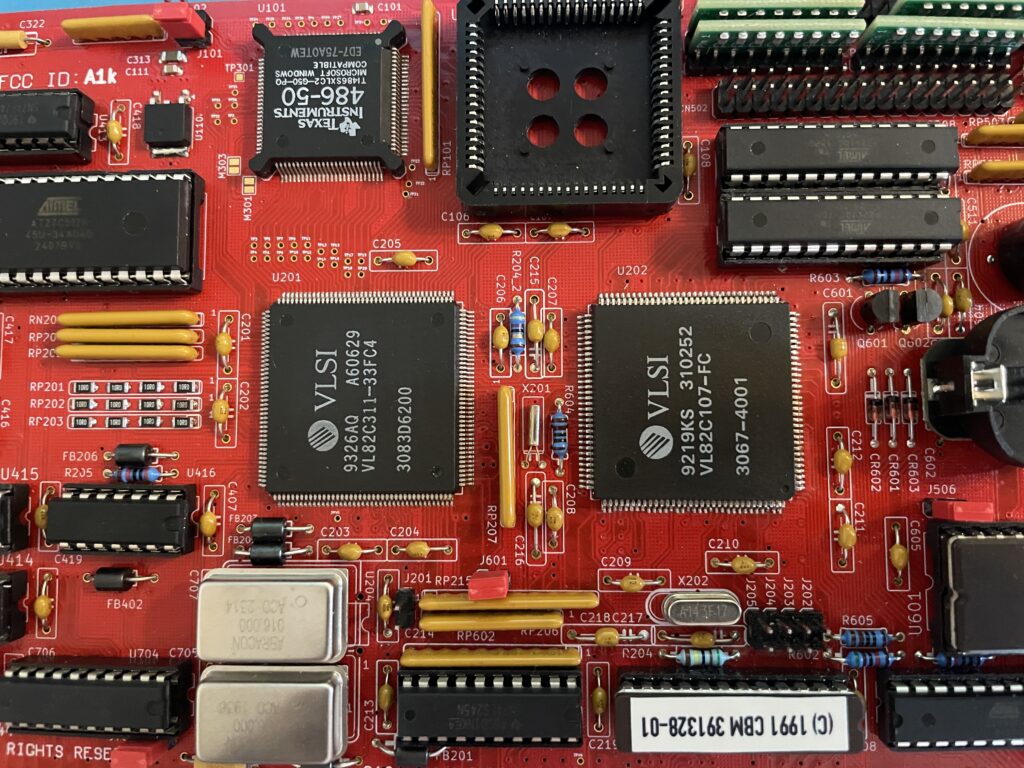
Update 20251222 – Here is A2386SX card replica #2
The second card was built without sockets
The second card is exactly the same as the last one, a different color though. This time it is black instead of red. Another difference is that I built it with less sockets this time.
Here is a closeup of the PC system chips.
Here are the PC system chips. Pay attention to the 486 chip. It was marked as a 486-66, probably an error when relabeling it.
Here are the Commodore chips and the PC memory in the form of ZIP ram (full 8 MB)
And here is the rare 5718 MOS chip and the less but still rare TC17G032AT chip. No PLCC sockets this time!
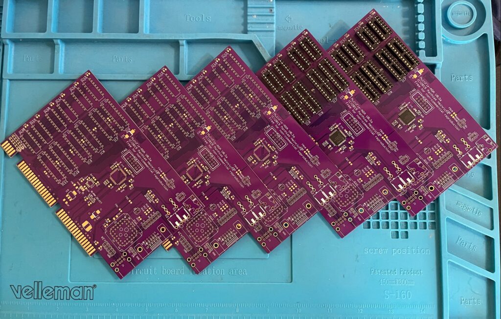
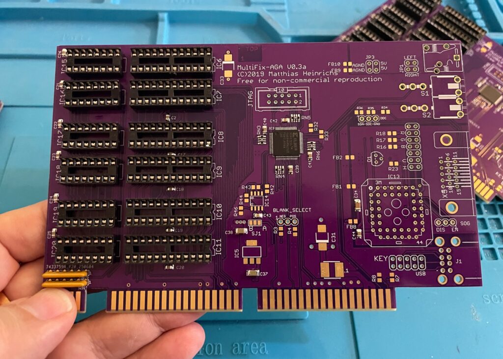
Here are five beautiful Multifix AGA purple PCBs. The Multifix AGA is a great Amiga scandoubler and flicker fixer. I will build two of these and sell the remaining cards once the built cards are tested, or do I build them all for myself (lol).
I plan to use them in the upcoming AmigaPCI (I will for sure build one once it is fully developed) and in my A4000T.