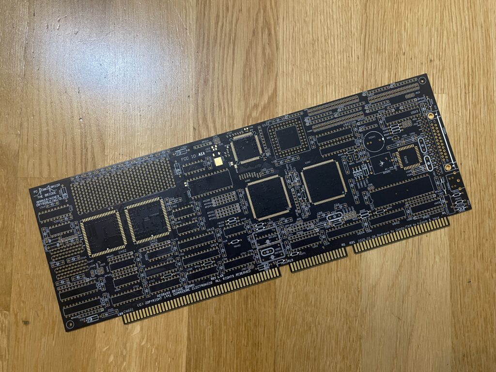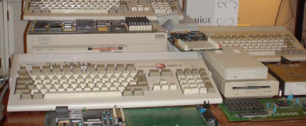
You may have seen my previous post where I did a test run on my ReAmiga 3000 that I finished earlier this year. If not, check out my post about my ReA3000 that I built in April here.
While I did do a test run in DiagROM previously I did not have a daugherboard for it so I just whent through the usual tests (successfully) and called it a day. This time I did a more comprehensive test session where I tested a Amiga 3000 daughterboard, a BFG9060, a GottaGoFaZt3r 256MB Z3 memory card, programmed and replaced the logic chips and also replaced some ICs that I had to use adapters for previously.
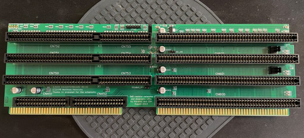
Amiga 3000 daughterboard
While my ReAmiga 3000 started up fine in DiagROM it failed to run with a Kickstart rom. I was puzzled about this since it was running fine in DiagROM. No matter what I tried I ended up with a black screen. Problem was solved by adding the daughtercard. Now Kickstart boot screen came up.
I am using a Matze A3000DB, more info on it here. This is just like a regular Amiga 3000 daughterboard but it also has I2C functionality so you can monitor temps. More info about I2C here, the added functionality is based on that project. So to be honest, I have not really fully understood I2C, perhaps I will do a deep dive in the future. I have an CPLDICY card I built last year and its neat to see temps. I am thinking this could be interesting to monitor if running a tight A3000 case with bad cooling.
Another note, this is a version of the Matze A3000DB with some added functions by kavanoz & CDH, see more here about this specific version of the daughterboard.
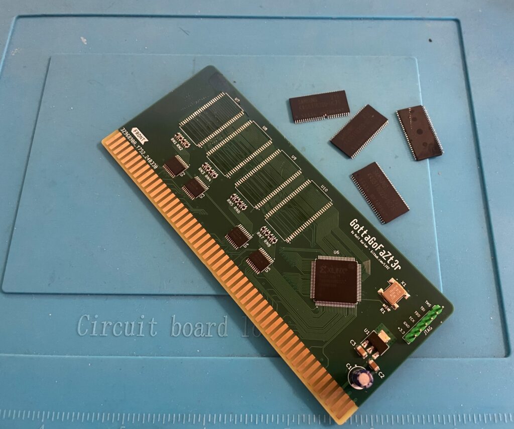
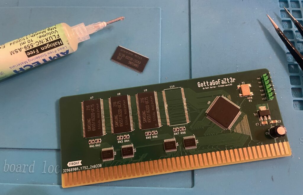
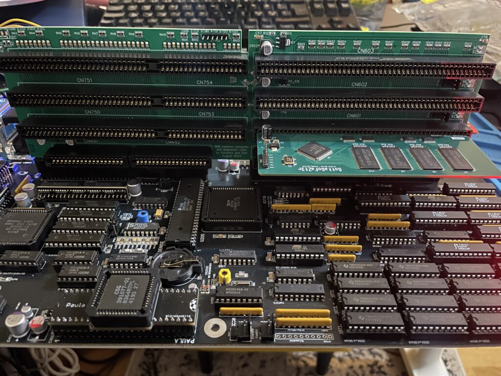
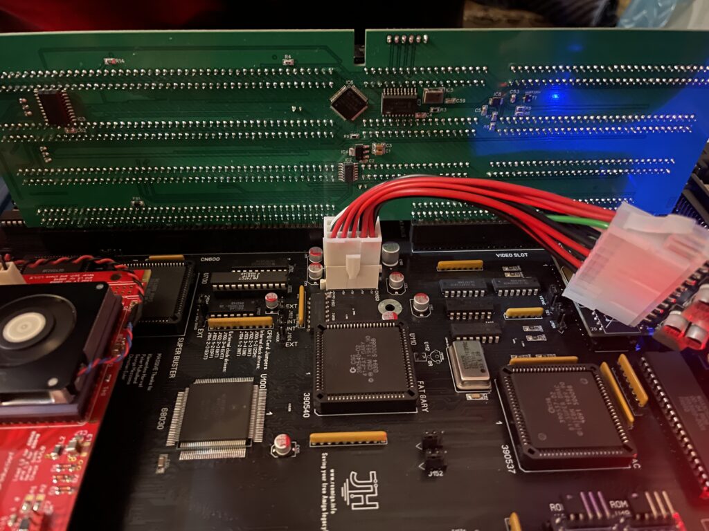
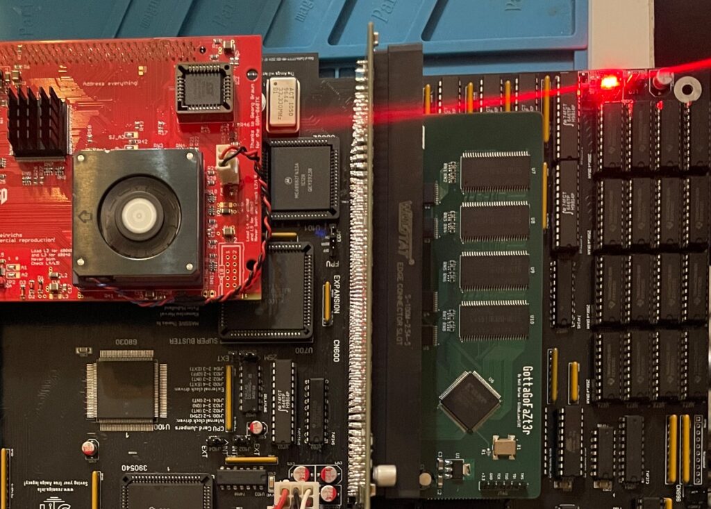
A GottaGoFaZt3r 256MB Z3 memory card was inserted and it was detected by DiagROM.
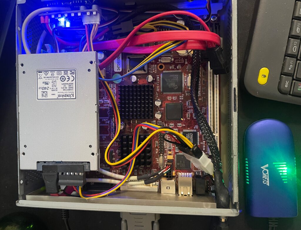
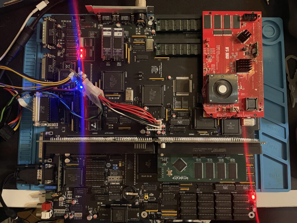
ReAmiga3000 + BFG9060 test, success?
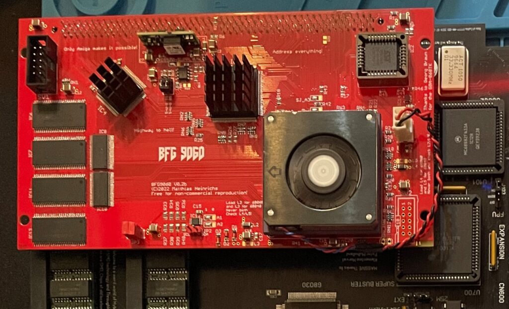
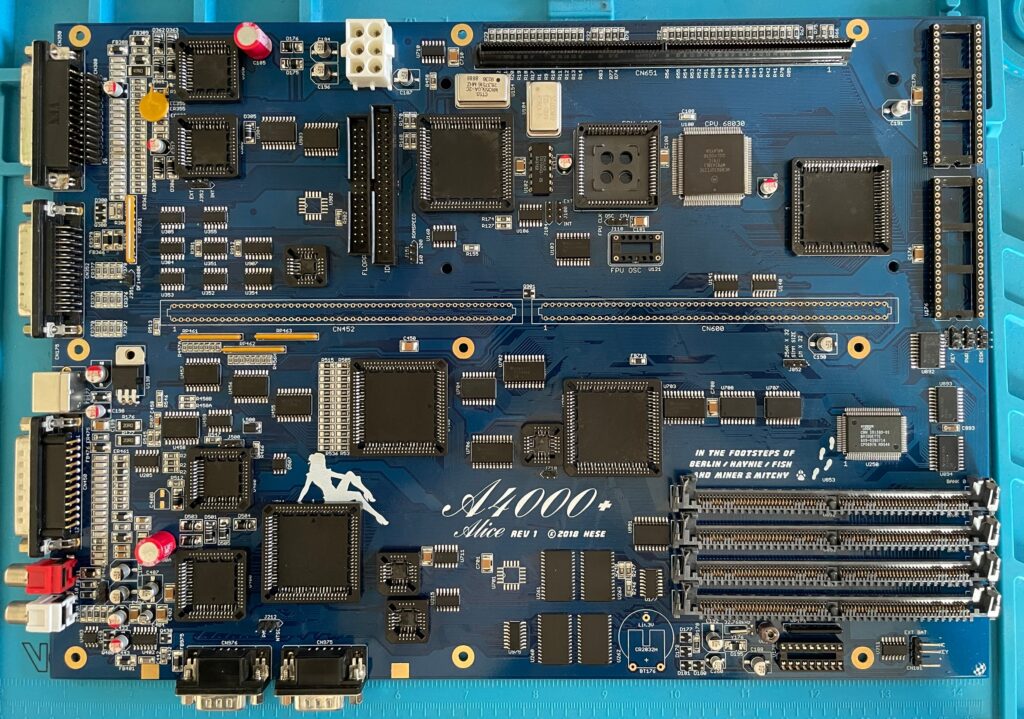
Recently I built an A4000D that failed to run with a CPU card. That motivated me to test my older builds with a CPU card to make sure they work properly with a faster CPU. The only issue I had was to figure out how to jumper the motherboard, then it was smooth sailings.
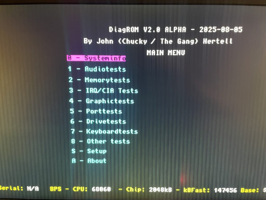
DiagROM identified the 060 and also the fast ram. Now I need to do a 6 hour fish render and stability will be tested (something to do for the future).
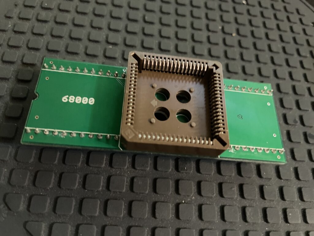
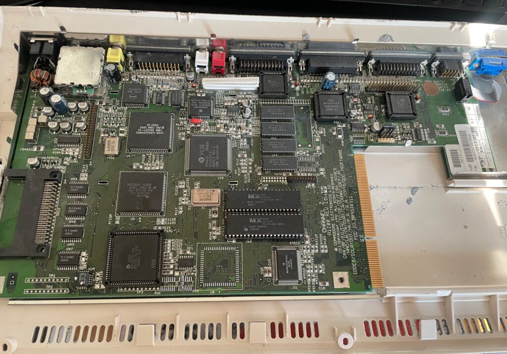
74FCT646 chip replacement
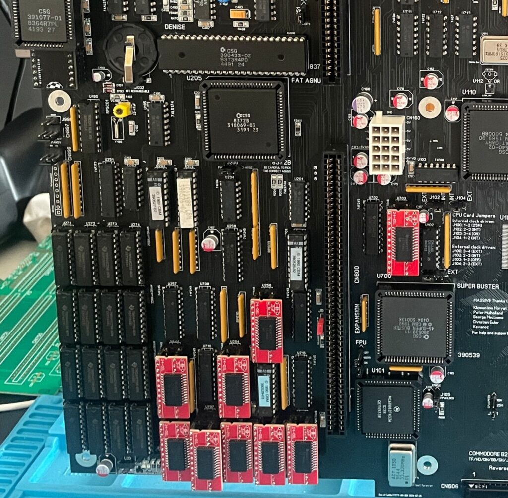
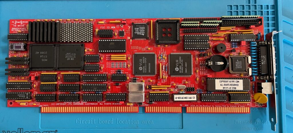
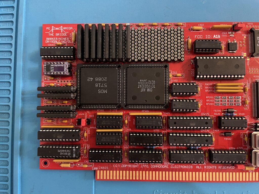
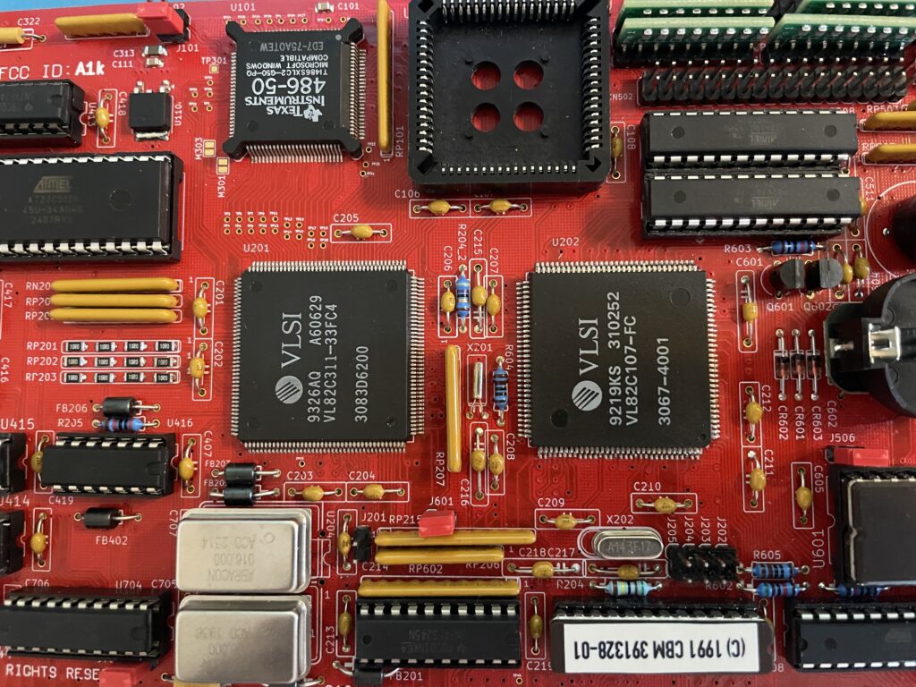
If you look at the BOM for the ReAmiga 3000 you can see that Chucky recommends replacing the 74F646S with 74FCT646. Currently 74FCT646 can only be found in SOIC-24 from Mouser and Digikey and not in DIP so you need a SOIC-24 to DIP adapter to use them. While the adapter worked fine I just felt it would look better to run DIP chips instead. I had an UTsource order going for my A2386SX order in the pipeline so I added eleven 74FCT646 chips to that order from UTsource. Why 11 when the A3000 only needs 9? Well two of them is going to my A2386SX boards.
The 74F646S chips actually runs hot, especially when there is 9 of them, that is something I noticed when using them from my donor machine. So it was a nobrainer to replace them with cooler running chips.
As I put in sockets for all the 74FCT646 chip adapters I am thinking of removing the sockets in the future and solder the chips directly to the motherboard for an even cleaner look. The ground plane in an A3000 is brutal though, not sure I wanna wrestle with this board desoldering stuff again. Desoldering the KEL 200 pin CPU slot was a nightmare.
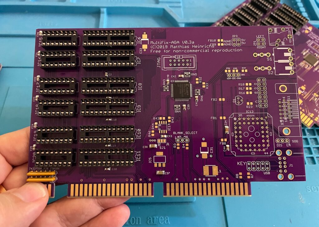
Programmed and replaced logic chips
There are four logic chips on the Amiga 3000. About 15 years ago I had the oppportunity to buy a broken Amiga 3000 cheap because it had a broken display output. Turned out it was because one of the logic chips was broken, so it was an easy fix to just replace one of the chips with a new one.
So to future proof this ReAmiga 3000 build I replaced the logic chips I got from the donor A3000 with modern alternatives and got the JEDEC files to program them with from here.
Next step
I hope I can find a case for this build, they are difficult to come by but occasionally you can find one. Actually wish I had one now as I would like to set it up to a running system!
C’est la vie…