A set of custom chips from an Amiga 1200 resting in a plate of IPA
Bought a rotten non working Amiga 1200 motherboard recently and spent the evening desoldering and cleaning up the Amiga custom chips. TBH I was only after the Alice chip… hope it works!
Update on the Amiga custom chips: 2026-02-01
Amazingly, all chips was confirmed working! Especially considering the motherbaord that I desoldered the chips from looked like this (warning):
A thick layer of dirt covering the A1200 motherboard. I especially like the unmatched Kickstart chips!
This is how I tested the Amiga custom chipset, I have an ReAmiga 1200 with sockets for the custom chips so I could just swap the chips on it and give it a go in Diagrom. I bought this Amiga 1200 motherboard built by someone else. I do not recommend building it with sockets, but for testing purposes it is fine.
I have worked on some small things here or there on my Amiga computers. Here are some noteworthy things that has kept me busy.
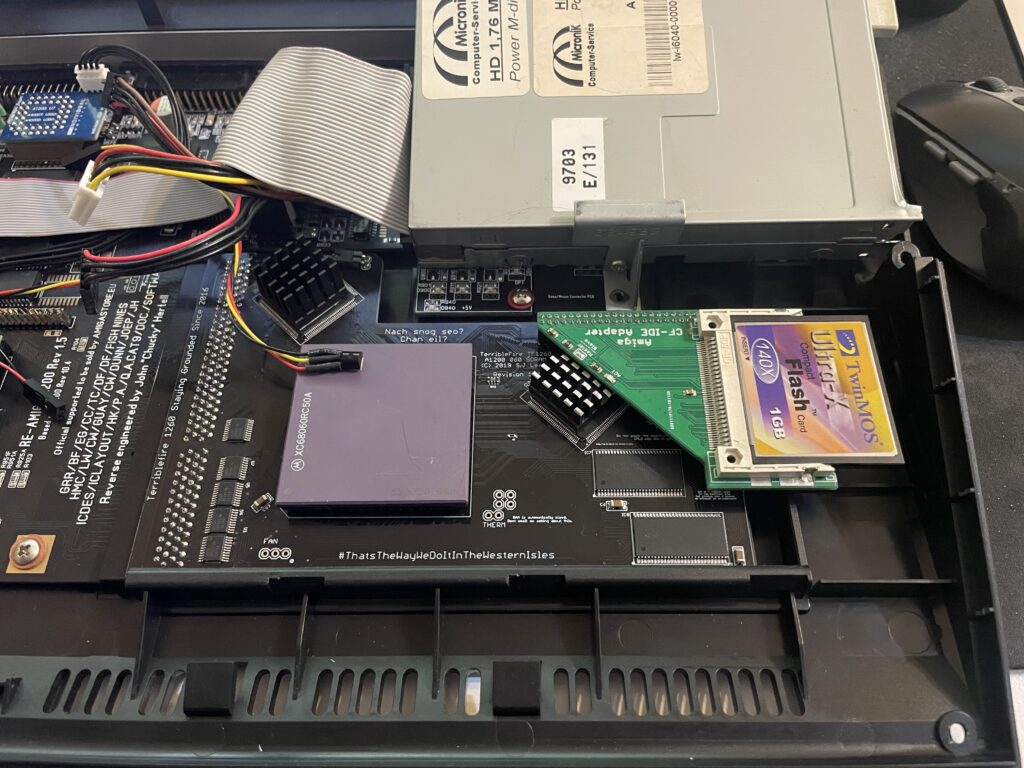
Installation of an 2.5″ angled CF adapter in my backup A1200
These angle 2.5″ CF adapters were popular 20 years ago
I found angled 2.5″ CF adapters on AliExpress. I have been looking for these for quite some time. They can not work if you have an Indivision AGA in your A1200 but if you do not have one they offer a great reliable way of running an internal compact flash drive in your Amiga 1200. There was only one problem:
This one has a pin blocked, probably to keep you from frying it by mounting it 180 degrees wrong
They came with one pin blocked. I used a small drill to drill into the blocked pin and realised that it was only the top layer that was blocked. Next step: try it out in my backup A1200.
How nice, a genuine C= Amiga 1200 case and keycaps
My backup A1200 has 3.1 Kickstart roms so I had to upgrade the Kickstarts before trying an Workbench 3.2 installation. So the next step was to flash some roms with AmigaOS 3.2.
FlashROMs are programmed with DiagROM and Kickstart 3.2
Here are the FlashROMs. I decided to flash DiagROM and Kickstart to them as they can hold two ROM images. It is very handy to have DiagROM availble if needed.
A white ReAmiga 1200 matches the case nicely
My backup Amiga 1200 looks like a regular A1200 on the outside but inside it is a white ReAmiga 1200 that I built a couple of years ago.
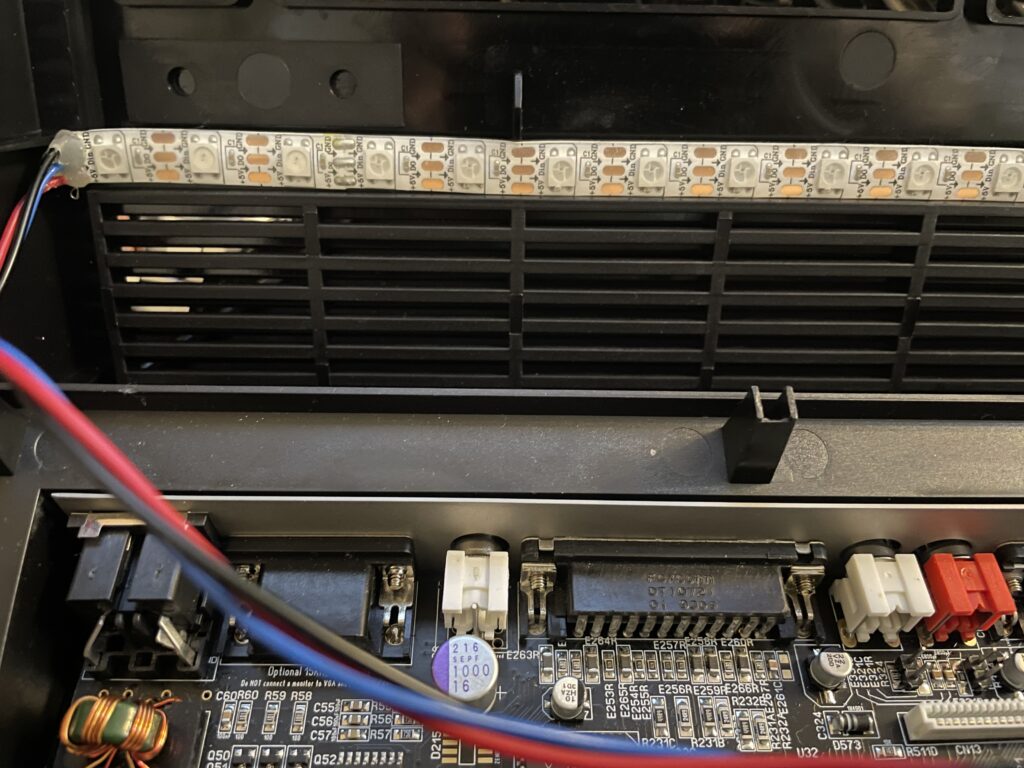
The more LEDs the better
Here the FlashROMs installed. But it failed to boot into the Kickstart screen, DiagROM worked though. So out came the T48 programmer and FlashROM adapter again. It was impossible to flash the FlashROM again. After 30 minutes of fail checking I realized that I used the wrong USB-A cable for the T48. After swapping cables the correct ROM image was flashed and everything worked.
The ReAmiga 1200 has a kickstart switch built in it
The ReAmiga 1200 has a nice Kickstart switch feature that you can enable. If enabled you can chose between two different ROM images through a jumper. If you do this with a FlashROM you do not need to jumper the FlashROM. As you can see, I never bothered to solder on the fan headers.
The angled 2.5″ CF adapter fits the A1200 motherboard fine
Here is the CF adapter mounted on the internal 2.5″ port of the ReAmiga 1200. Booting off of a WB 3.2 installation it worked fine.
I am using an old school external 23 pin scandoubler, thats why the image is a bit dull
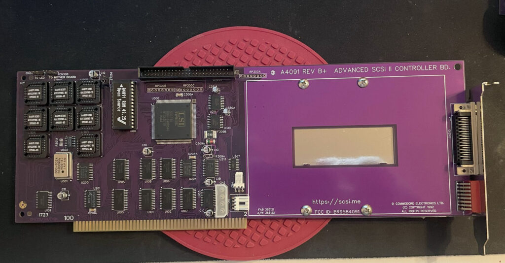
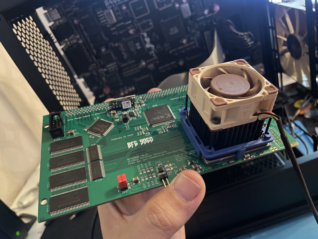
Making the ReA4091 work with a BFG9060 clocked at 100 MHz
ReA4091 SCSI2 Zorro 3 card
I had problem with my ReA4091 SCSI card when running my BFG9060 68060 turbo card at 100 MHz. The Amiga 4000TX worked fine if the BFG was clocked at 50 MHz but at 100 MHz the system refused to run stable giving me filesystems error instantly in Workbench.
This is not a new problem as many other has had it. But at the same time, many have gotten A4091 and a BFG with a 060 clocked at 100MHz working without trouble.
I got a heads up about a thread on github discussing possible solutions to this problem. You can find it here. One suggestion there is to reprogram U305 with the file from here.
Apparently this fixed the problem for the user who suggested it on github with a drawback of 10% less SCSI performance.
BFG9060 with 68060 rev. 6 clocked at 100 MHz
I did not have anything to lose so I decided to give it a go by flashing the little PLCC chip with the file suggested. To my surprise it actually made my hardware setup stable again at 100 MHz! Now that I have put in a few hours in my system I can confirm that it runs stable (and now more than 6 months later I can confirm that it has been working great).
This particular build consists of an A4000TX, BFG9060 with a rev.6 68060, ReA4091 with a ZuluSCSI compact, there is also a ZZ9000 graphics board in the setup. It is my main setup.
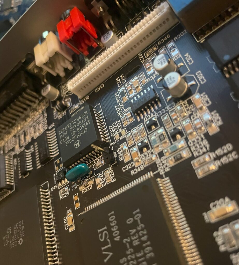
Solas + ISA board installation in my A4000TX
I have a Solas LED controller in my A4000TX, it is hooked up to an ISA carrier and is connected to the clock port on the Zorro-LAN-IDE card. It took a while to figure out how to connect them together and to get sound into the Solas. But after tinkering with it for a few hours it is working fine now.
The sandwich card of the Solas carrier and Solas is too thick though, making it difficult to run a full size Zorro card over it, I am thinking of soldering them together to decrease the height of the card sandwich. It could either be the greatest thing ever or the greatest disaster ever, I will need to flip a coin on how to proceed with this idea.
Second A2386SX board built and tested
I like to build things I like in pairs that is why I did not hesitate when I was given the opportunity to build a second A2386SX clone again. You can see some more pics in the previous link. I do not think I will build more of these boards as they have given me a tough time both in getting them working and in sourcing components for them.
A4000T AT case mod
Mid size PC AT case from 1998
I did not hesitate to jump on the train when an A4000T replica PCB was offered for sale on Amibay a few years ago. Building it was a lot of fun and also fascinating. The A4000T is after all the final official 68k Amiga computer released.
I was too naive expecting a case to show up by itself. Now I realize it might never show up so I decided to look for solutions. There are ATX options but I wanted to try an old AT case first.
The universe was aligned with my third eye and suddenly an AT case manifested itself on a local trading place. But the struggle is real, nothing comes without pain and struggle. The A4000T motherboard is huge, it wont fit this case without some cut fingers on old sharp PC case sheet metal edges and serious case modding. And I hate hardcore sheet metal case modding and cutting my fingers on old shitty PC cases.
The A4000T motherboard actually fits inside this case, but it will take some serious case modding to make it happen!
But once modded though, the 5.25 bays the case has wont be usable any more. It wont be able to take an AT or ATX PSU anymore either. But hey, when it is fully modded, at least I got a case for the A4000T where the daughter boards line up perfectly on the back of the case. I just need to figure out how to mod this case in the simplest way possible.
Alicia is an Amiga 1200 clone in the popular Mini-ITX form factor. It is a nice DIY project you can buy as a semi built PCB. As I had previously built a couple of Denise A500+ clones, deciding to build the Alicia 1200 was a no-brainer and I think I was not alone in that thought as the interest around it has been great! Read more about the project here.
I remember fondly when the Mini-ITX form factor was released to the public around the new millennium. It was a really exciting time in PC hardware and watching the new tiny form factor it grow and become an established platform has been a pleasure to see and experience since I have been on the Mini-ITX train many times since then.
But to be able to see, build and own Amiga systems in this small form factor with real Amiga chips is the icing on the cake – Amazing!
Denise, Alicias little Amiga sister
Denise A500+ ITX with TF536, Denise NIC, Mini Graka, Indivision ECS v3
I have not written a lot about Denise, the A500+ clone, here on my blog even though I have wanted to do that for some time.
I “blame” the beginnings of my interest in this “wallet busting” hobby on this specific project, YOLO. So expect a better post later sometimes. I remember watching plenty of YouTube clips of doing SMD soldering with a soldering iron 5 years ago and asking myself, “can I really do it?”, then I ordered a Denise board and a package from Digikey. Unpacking the first 0805 capacitor, I questioned what I had gotten myself into back then.
Anyway, I think it could be interesting to show off my Denise build before moving on to the Alicia 1200.
The Denise is an Amiga 500+ clone in Mini-ITX form factor, it has all the regular chips the A500+ has and also two “dumb” (as in no Buster) Zorro 2 slots. The PCB is jam packed but everything is beautifully laid out on the board.
Point I wanted to make was that this has been a very stable Amiga and it is awesome to have an Amiga with a small graphics board, scandoubler, NIC and 030/HDD in a standardized small form factor – That it is Mini-ITX is just icing on the cake.
To think this kind of hardware was A2000 territory yesterday is crazy. Anyway, let’s move on to the Alicia Amiga 1200 AGA clone…
Approaching the Alicia 1200 Amiga 1200 clone build, what have I gotten myself into?!
Alicia 1200 is a small PCB and most of the stuff for the build fits in this small box!
Alicia 1200 is a kit, so one have to build it oneself. I have built a few Amiga kits myself as stated above so I did not expect any problem with the Alicia build. I usually build my projects from scratch, but in this case it has all the passives and common chips mounted. This saved a ton of time.
Lets talk PLCC sockets and chips
I decided to build my Alicia without PLCC sockets. I have a technique that works really well for soldering PLCC sockets without removing the inner part of the socket. In my experience soldering PLCC chips directly to the PCB makes for a more secure connection and eliminates any potential contact issue. I feel hot chips such as Paula, Lisa and Alice runs cooler when soldered directly to the PCB. I do have a few Amiga motherboards with full PLCC sockets for testing purposes.
Soldering the PLCC chips might be difficult if you are not used to doing them. I solder the PLCC chips with a relatively large hoof tip. Not saying the hoof tip is the definitive success factor. My success is probably from doing a LOT of PLCC chip soldering and getting used to a specific technique.
Difficult to find parts aka “ahh shieet here we go again…”
Most parts for the Alicia 1200 can be taken from an Amiga 1200 or can be found on Ebay, Amibay or from the “usual” places.
You will need the full Amiga 1200 chipset, including Motorola 68020, Budgie and A1200 Gayle. You will need an ADV101 or VP101 but you wont need the keyboard MPU. Memory can be taken from an Amiga 1200 too (but pay attention, some revisions come with incompatible memory that physically won’t fit). If you want to run the RTC you need a clock chip.
A 23 pin video connector is not needed and in fact can not be used, instead Alicia uses a regular VGA socket, so you have to make your own RGB cable if you plan to use it with SCART. You will need a PCMCIA connector, but that can also be take from an A1200 motherboard (hot air is your friend).
Everything else can be ordered from Mouser or Digikey.
So lets get the soldering iron warm…
Budgie and Motorola 68020 are done, drag soldering is your friend!
The first parts I soldered was the Budgie and the Motorola 020 CPU, they are both surface mounted chips and where desoldered from an Amiga 1200 motherboard. I actually did not know if they worked or not, but as they are mounted in a good position on the motherboard I could always desolder them and replace them if they failed to work.
Lets add some memory to the Alicia 1200
SOJ40 memory is soldered to the Alicia 1200 motherboard, flux is your friend in this case
You may have built a ReAmiga 1200 and struggled with the memory, I have. It is difficult to do a good job when the chips sit so tight together. I am not a fan of using hot air to solder them. Thankfully on the Alicia 1200 the memory chips are generously spaced leaving plenty of space for my preferred hoof tip technique making this task very enjoyable. This shows in the clean result.
Lets add some PLCC chips
First PLCC chip, Gayle, is soldered to the PCB, only six more to do!
Now its time for some PLCC chips. I have nailed the technique for soldering PLCC chips. But the challenge is getting them aligned correct on the solder pads so the joints form a straight line. I got successful with the first chip at the top left, Gayle. If you fail to align the chip it will still work but may look a bit off. Depending on your level of OCD this might be totally acceptable though.
All Amiga chips are now soldered to the board. But there are still plenty to do.
Here are all the PLCC chips soldered to the Alicia 1200 PCB. I think this was around 4 hours of work in total. No idea if it works and no way of testing it yet. Let’s hope it works.
And lets add some ports and connectors
Almost ready for the first test run, what if it does not work!
I am not alone when I say there is an universal curse around BOM orders. It is an unofficial rule more than an exception that it is derigeur to miss to order some small part or important part. In this case, it was a small chip on the bottom of the PCB and the ATX power socket.
First test run of Alicia 1200 A1200 clone
It is difficult to see, but there is a blue Indivision MK3 mounted on the Alice chip
Once I got the missing parts I was eager to try Alicia 1200 out and see if it was working. And it was here I stumbled upon a problem, I did not have a suitable screen or RGB-SCART cable to test it. I thought I could use a 23 pin to VGA converter and hook up my old RGB-SCART cable with a 23 pin connector, but it did not work.
Just to verity that it worked I opted to do a testrun with a temp solution: using my Indivision MK3 that I have in my Amiga 1200 so I could get HDMI output.
Update: I have since built a VGA to SCART cable according to the instructions in the manual and I recommend everyone to do that to test that the port is working.
And it works!!
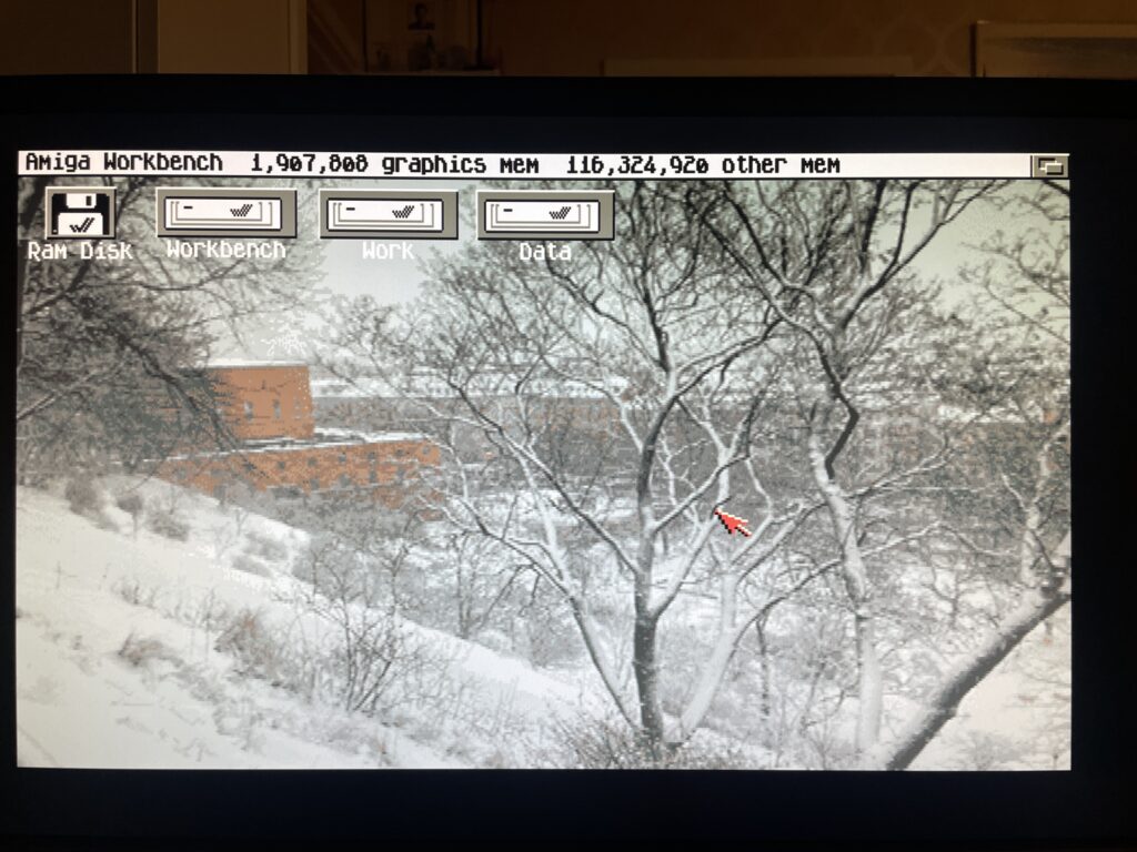
Testing AGA chipset with DiagRom
DiagROM boots and all tests checked out fine! The image above does not do justice to the image quality of the Indivision MK3, I was almost ready to fork out cash for a second one! This is a beautiful hardware combo if you want AGA only.
Sound played fine on the Alicia 1200 when testing channels in DiagROM. I think the sound circuit is the same on the Alicia 1200 as on the Denise as i recognice a few of the parts on the motherboard here.
I would descibe the sound on the Denise as slightly tinny, metallic or a bit more clean than a regular Amiga 500 or Amiga 1200, it is an interesting attribute of these motherboards and adds another dimension to the sound output of the Amiga. Cant wait to try it out with the Sound Enhancer.
Lets finalize the Alicia 1200 Amiga A1200 clone build
Alicia 1200 fully built!
Once Alicia 1200 was fully tested I could go ahead and add the final connectors including the PCMCIA slot (that I cut down to make it shorter since it sticks out a lot).
So let’s end this post with some features that Alicia 1200 has that a genuine Amiga 1200 does not have. First it has a real time clock. Then it has a video slot on top left side. There are no devices to connect here today, but there are rumors of scandoublers and other exciting stuff. Lets see what the future holds. I have suggested a 3DFX card numerous times lol.
The Alicia 1200 Tornado slot CPU slot adapter.
The larger slot is the Tornado slot, as you can see on the image above it is converted into the Amiga 1200 slot. Hopefully someone will release a direct mount CPU card for the Alicia 1200, if not, we can just use the converter above and run our TF1260s or PiStorms or whatever will be available directly on that.
Next steps!
Let me follow up in the future what case I will chose and what CPU card I will use. I am leaning towards PiStorm, but the beauty of a 060 in this little system is very tempting, almost too tempting to resist. And with the way the CPU card is mounted, there is plenty of space to run a badass heatsink over the 060 unlike in an Amiga 1200… you can be sure I will follow it up here in the future!
This Amiga 1200 was painted in an unusual color (and paint).
I won an Amiga 1200 on a local auction website. I put in a max bid but surprisingly it got sold for cheaper than I anticipated. I think it was for a couple of reasons. First the case was painted in a weird cement like textured paint, more on that later, secondly it was sold as-is and not working. I have heard of a new Mini-ITX AGA A1200 clone being developed so this broken A1200 will be the donor for that future project (if the chips works).
The value in this computer (for me) lies in its chips. I am mainly interested in Alice, Lisa, the two CIA chips and the Paula. I am also interested in the memory chips as those can be used on various projects. There is some value in the 23-pin video socket also.
I did some math and took a gamble on both winning the Amiga 1200 and on the chips working. As the CIA chips, the paula and Alice has been socketed, that is a clear sign someone has messed inside this A1200 before. Could both be good news or bad news as sockets can be the reason for the computer not working.
Anyways, here is how I calculated the value:
Alice: 100-135 euro
Lisa: 20-35 euro
CIA (2x): 35-80 euro
Paula: 25-35 euro
Memory (4x): 10 euro
23-pin D-SUB: 10-20 euro
Total min: 200 euro Total max: 315 euro
Note, I am not calculating this on Analogic prices!
Lets hope the chips are working, will test them later in the year as the motherboard has been cleaned and is archived in my Amiga hardware stash now.
And the reason why i dont count any value in the case: it was sadly painted in this horrible “paint” that gave me a terrible itch in my fingers for two hours after touching it for a few minutes. I will probably throw it away in the trash since I suspect the paint is toxic.
Changing memory chips on a GottaGoFaZt3r
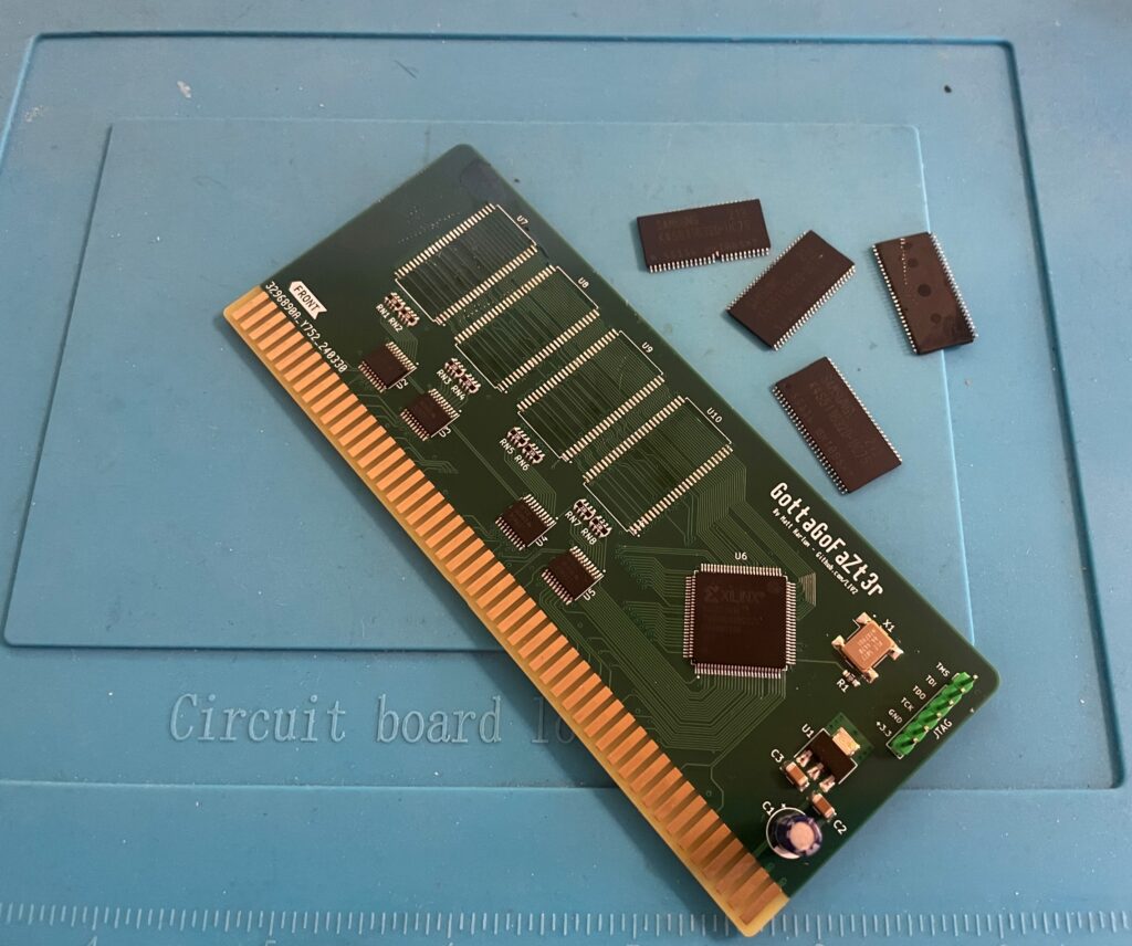
Removing memory chips from the GottaGoFaZt3r Zorro 3 Amiga memory card
I built two GottaGoFaZt3r Zorro 3 memory cards late last year, only one card worked. The other refused to work, it still showed up as “working” in my Amiga 4000TX but the memory was nowhere to be seen. I got the recommendation to check for errors in the memory chips one by one. Instead of doing that I got four new chips instead from a reliable source.
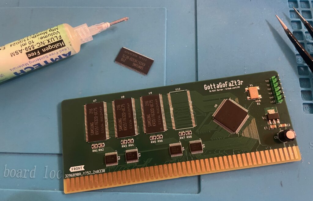
I removed the memory chips with a hot air station. Then I cleaned the pads and soldered on the new memory chips.
Soldering new memory chips on the GottaGoFaZt3r Zorro 3 Amiga memory card
And once all chips was replaced the card finally worked 100%.
Both cards are built as 256 MB cards. 256 MB might seem like a lot of fast mem in an Amiga but it is actually very usable. I run a bit more buffers on my partition than a stock HDD setup so that consumes some of the fast mem. But the main usage is off course to have a large RAM disk (as there are already 128 MB on the turbo card).
And here is a pic from sunny Stockholm today!
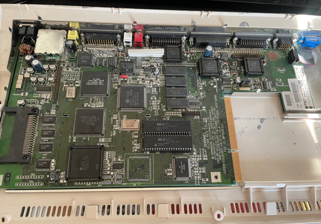
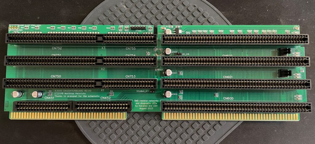
Amiga 3000 daughter card
And finally all parts for my ReAmiga 3000 build is now soldered with the daughter board being finished. It still needs to be flashed, but that will happen another day!
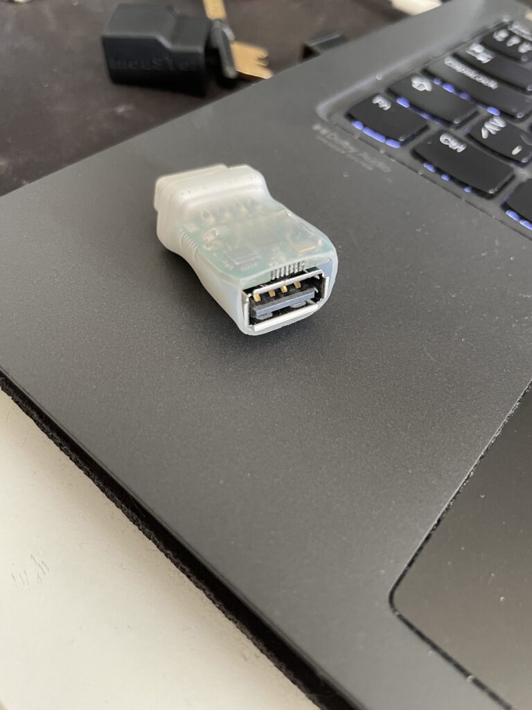
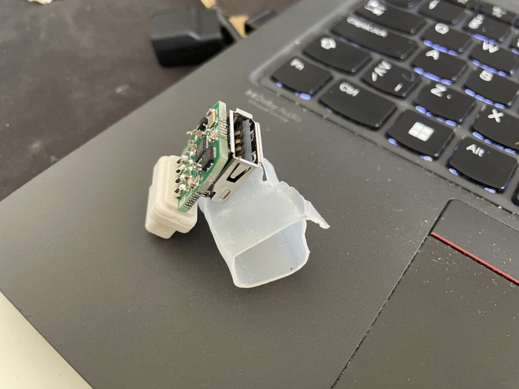
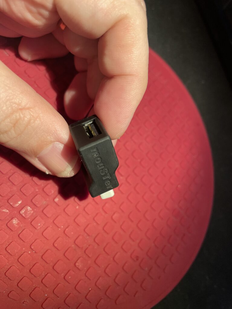
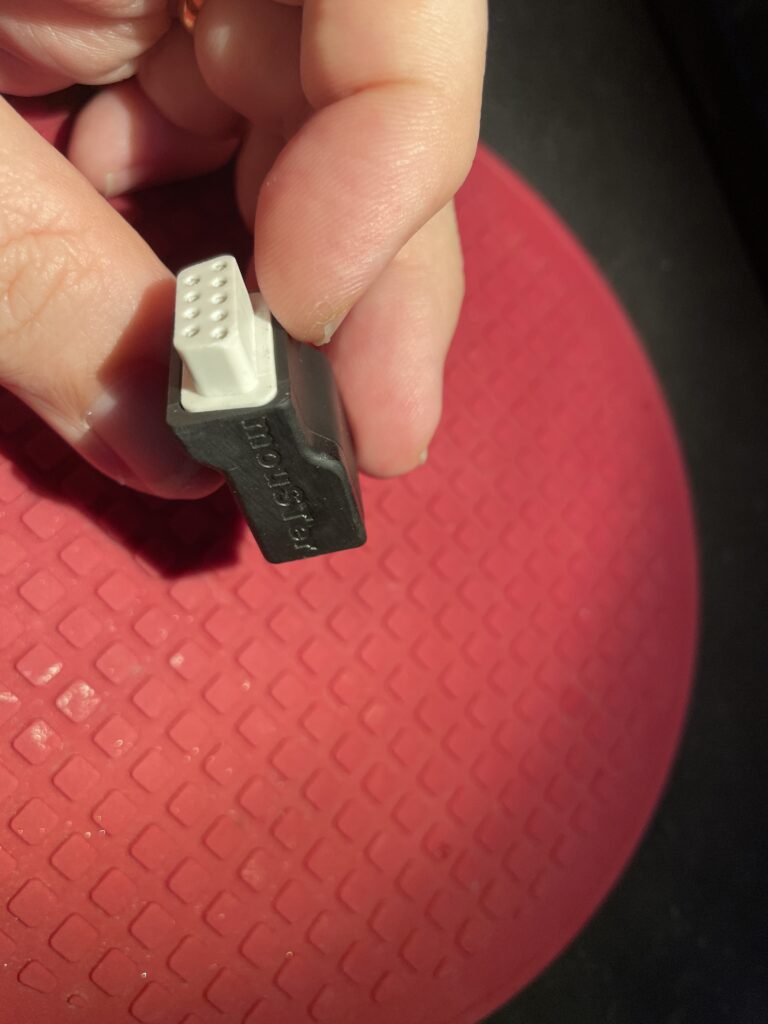
MouSTer 3D printed shell
I have used a MouSTer USB mouse adapter with a wireless mouse on my Amiga for 3-4 years and I have been very happy with the adapter. Only thing I was not happy with was the heat shrink tubing that was used as the shell. It looked so cheap.
I was surprised to find a 3D printable shell for it online. I ordered one to be printed on JLC (in resin). I got a couple of warnings that the walls was too thin and may not be able to be printed. But all worked out better than I anticipated!
It looks so much better with the 3D printed shell.
The fit is perfect. I just superglued the two halves together, there are no user servicable parts on the MouSTer so no point in making it possible to open the case again.
I dont remember exactly where I found the files but you should probably be able to find them here if you search for them.
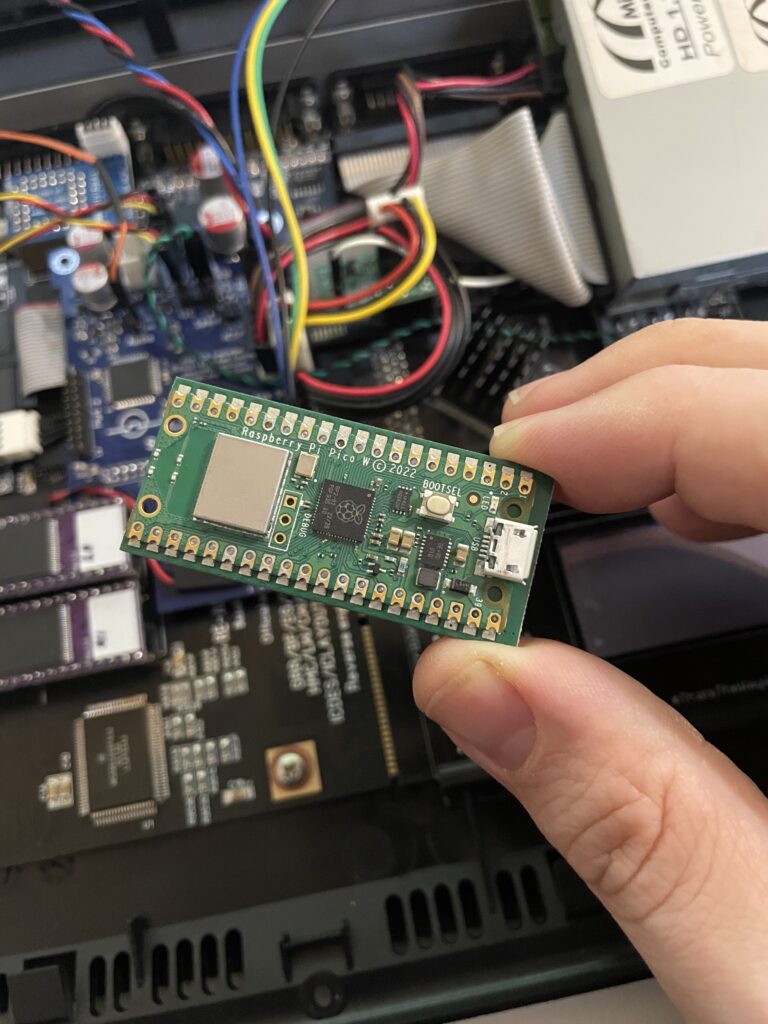
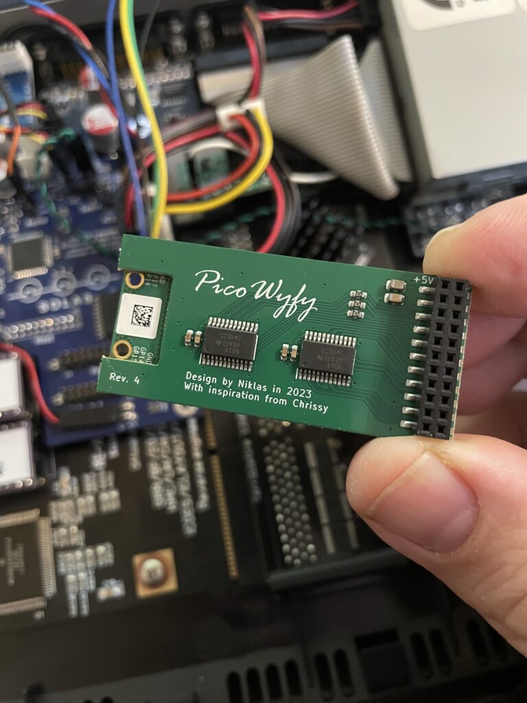
PicoWyfy means wifi for the Amiga hooked up to the clock port!
I just got a PicoWyfy and has spent a day playing around with it in my Amiga 1200. I am very happy with this device as it has helped me get my Amiga 1200 online and onto my network at home.
The PicoWyfy is a “wireless network interface controller” and it connects to the clock port on the Amiga (either on the motherboard or on a Zorro card or other clock port solutions). Read more about PicoWyfy here, you will also find instructions on how to get one there.
Wireless networking has been a possibility on the A1200 and A600 for a long time on the PCMCIA port. I got a NetGear MA401 for this purpose years ago, but the though of having an ugly PCMCIA card sticking out of the side of my Amiga 1200 meant I never bothered to install and configure it. I would rather just put all my files I wanted to transfer on a CF card on my PC and put the CF card in a PCMCIA to CF converter making it easy to copy files of off the CF card to the Amiga HDD.
In comparison with PCMCIA solutions the PicoWyfy is placed on the clock port, so it is fully internal. As you can see on the images, the PicoWyfy is based on a Raspberry Pi Pico W.
Back of the PicoWyfy card
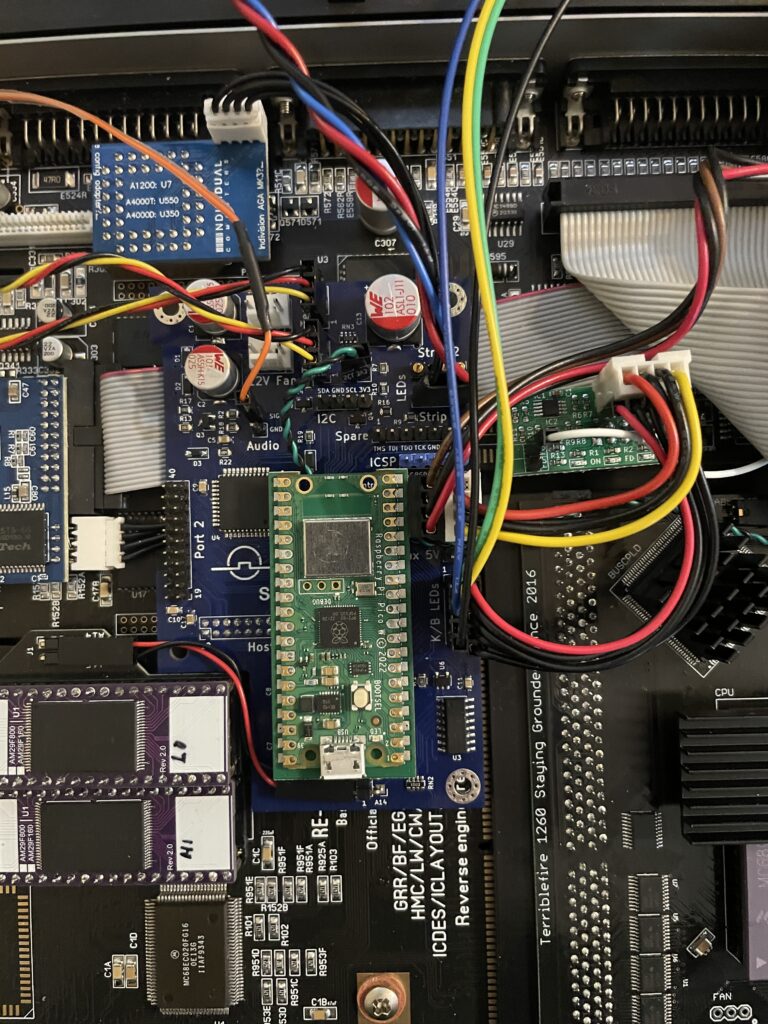
Installing PicoWyfy in my Amiga 1200
PicoWyfy installed on the Solas that is installed on the A1200 clock port
Installing the PicoWyfy in an A1200 was very simple. If you are reading this, chances are that you already know about the clock port in the Amiga 1200 and what to take care of when mounting hardware here. So no point in going through that. If not, I will eat my hat.
My Amiga 1200 already had a Solas RGB LED Amiga controller inside it that was placed on the clock port. The Solas has a clock port expander integrated into it, so installation was as simple as putting the PicoWyfy on one of the free clock ports on the Solas (and configuring the PicoWyfy for that clock port address). Where to put the actual clock on the Solas is another issue I will have to figure out in the future as the PicoWyfy takes up space for it.
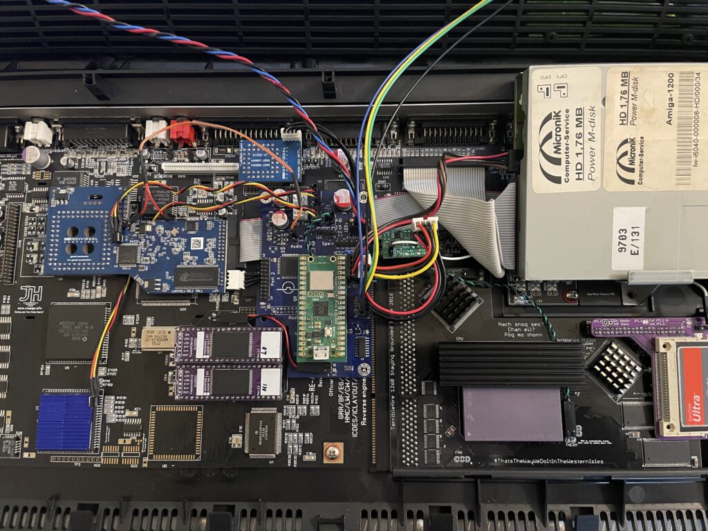
Overview of my Amiga 1200 with PicoWyfy installed
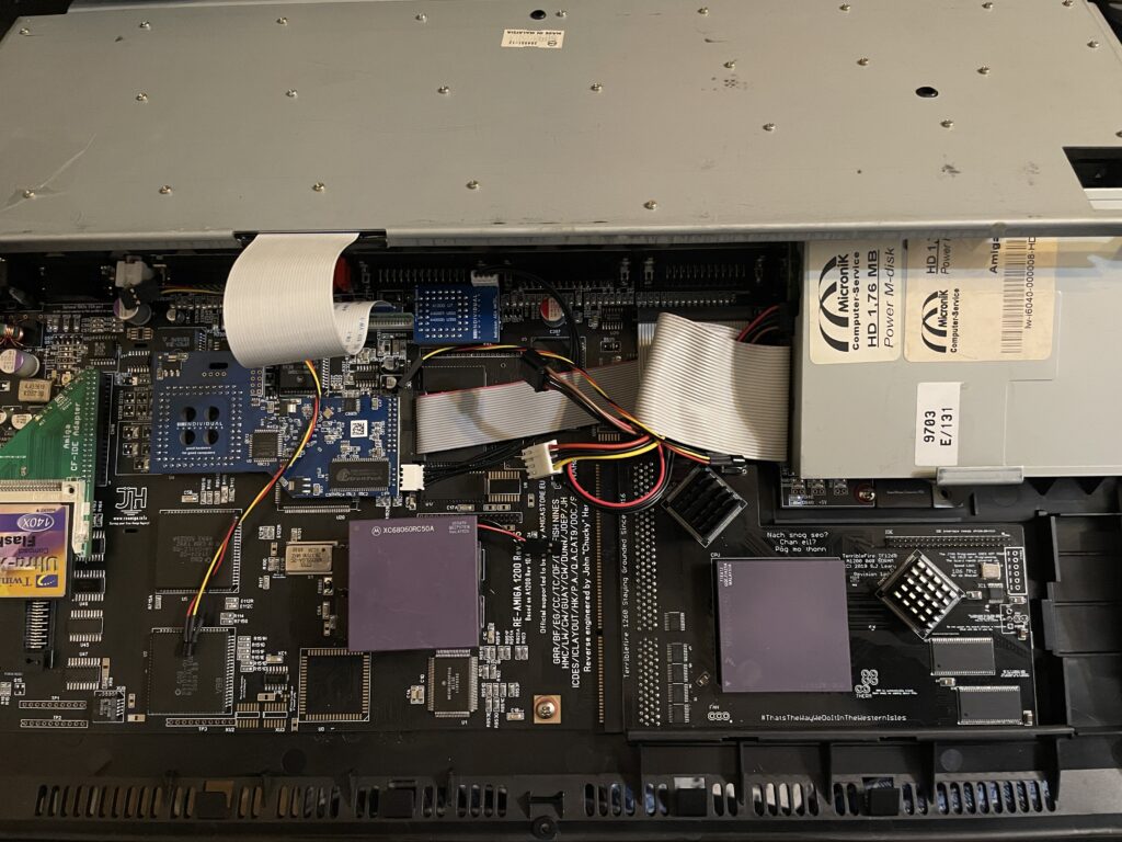
As the A1200 case is plastic, there wont be any signal strenght problems. If you wonder what I have in my (main) Amiga 1200, specs are listed below:
ReAmiga 1200 1.5 motherboard
Indivision AGA MK3
TerribleFire 1260 @ 100Mhz / 128MB
FlashROM
Solas RGB LED controller
LED adapter (so that TF1260 IDE activity is seen on the case LEDs)
Buffered CF interface / 4GB CF
MicroniK 1.76 MB floppy drive
And finally, the latest addition: PicoWyfy
Setting up the software and drivers for PicoWyfy
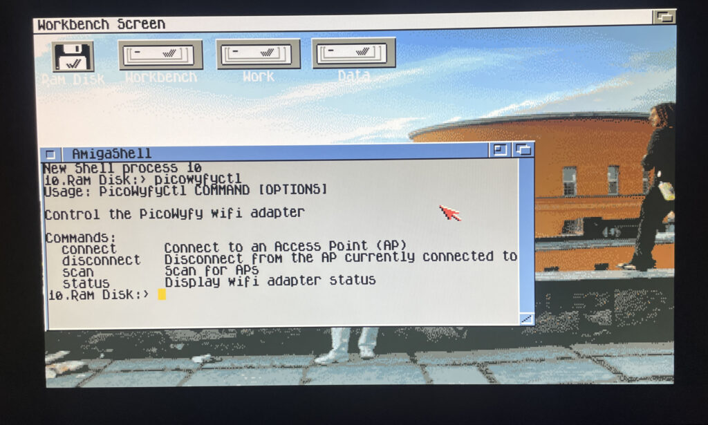
Picowyfyctl is the program that can control the PicoWyfy on the Amiga
Installation of the PicoWyfy is straight forward. All you have to do is put some files in the right places in the Workbench drawer. Then it is possible to run the program picowyfyctl to scan for wireless networks, connect or disconnect to wireless networks and to view status of the PicoWyfy. There is no GUI here but it is so simple to configure you wont need one.
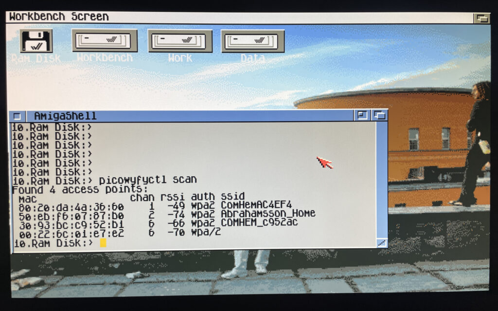
Running a scan on the PicoWyfy to find wireless networks to connect to
In the picture above I have run a scan to look for wireless networks to connect to in my area. I can see my WIFI network here so thats what I am going to connect to.
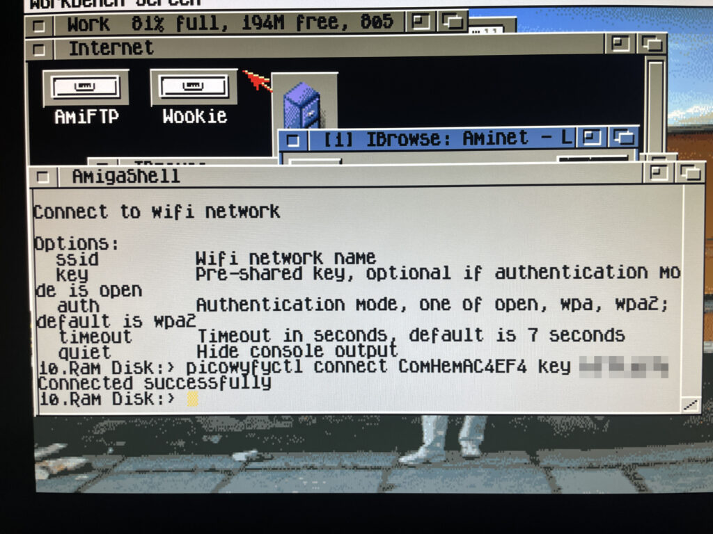
Connecting to a wireless network on the Amiga 1200
Here I am connecting PicoWyfy to my home network and as you can see, the connection attempt was successful! I have also removed my WIFI password, if you must know it is “12345679abcd”.
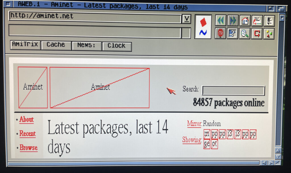
Testing a browser online on the Amiga 1200
Off course I have to test the connection by browsing the information super highway in an ooooooold version of Aweb, if you type something wrong in the URL field it goes to Altavista by default. How nostalgic. As the modern web runs on HTTPS the browsing session was very limited, but I think it is possible to set up HTTPS in some way or another. Possibly would need to investigate this.
But browsing the web wont be my main activity on the A1200 other than browsing Aminet – Having access to Aminet directly from the Amiga 1200 is such a luxury!
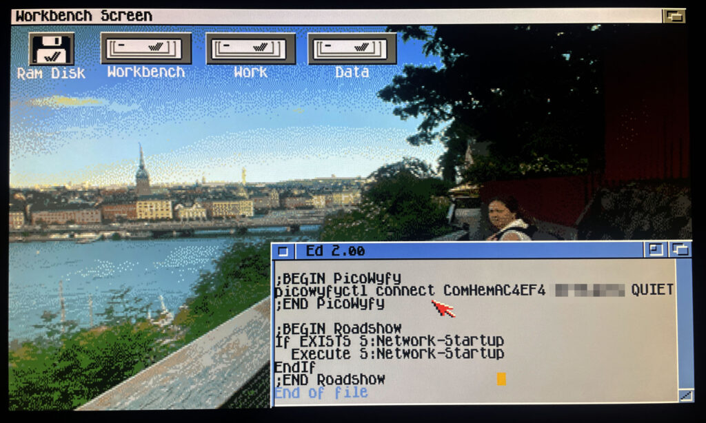
Adding lines to user-startup to connect to a wireless network on startup
I should mention that I use Roadshow as the TCP/IP stack. It is a great modern TCP/IP stack for the Amiga. Once everything was working I wanted my A1200 to connect to the wireless network automatically at startup. To do that it was as simple as adding the line: “picowyfyctl connect ssid key quiet” before the TCP/IP stack was called in s:user-startup.
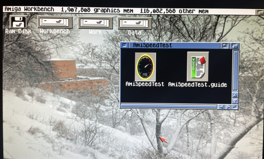
Trying out the program AmiSpeedTest to find out how fast the network is
So lets test how quick the card is on my system. There is a piece of software on Aminet called AmiSpeedTest you can use for this. Here is the URL.
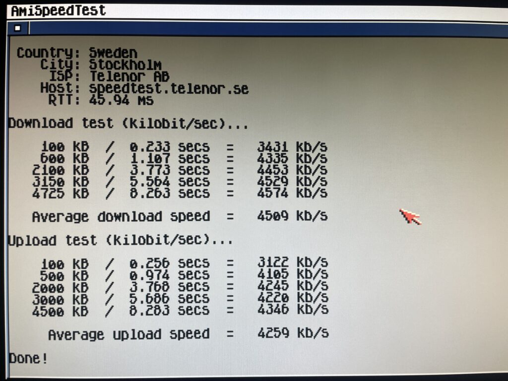
Running a test in AmiSpeedTest
So here is the test done. To be honest here I dont have a clue how good or bad these results are. Downloading stuff from Aminet is fast though so I am happy. Will test some transfers between my workstation and A1200 in the future also.
Average download speed was 4509 kb/s and average upload speed was 4259 kb/s
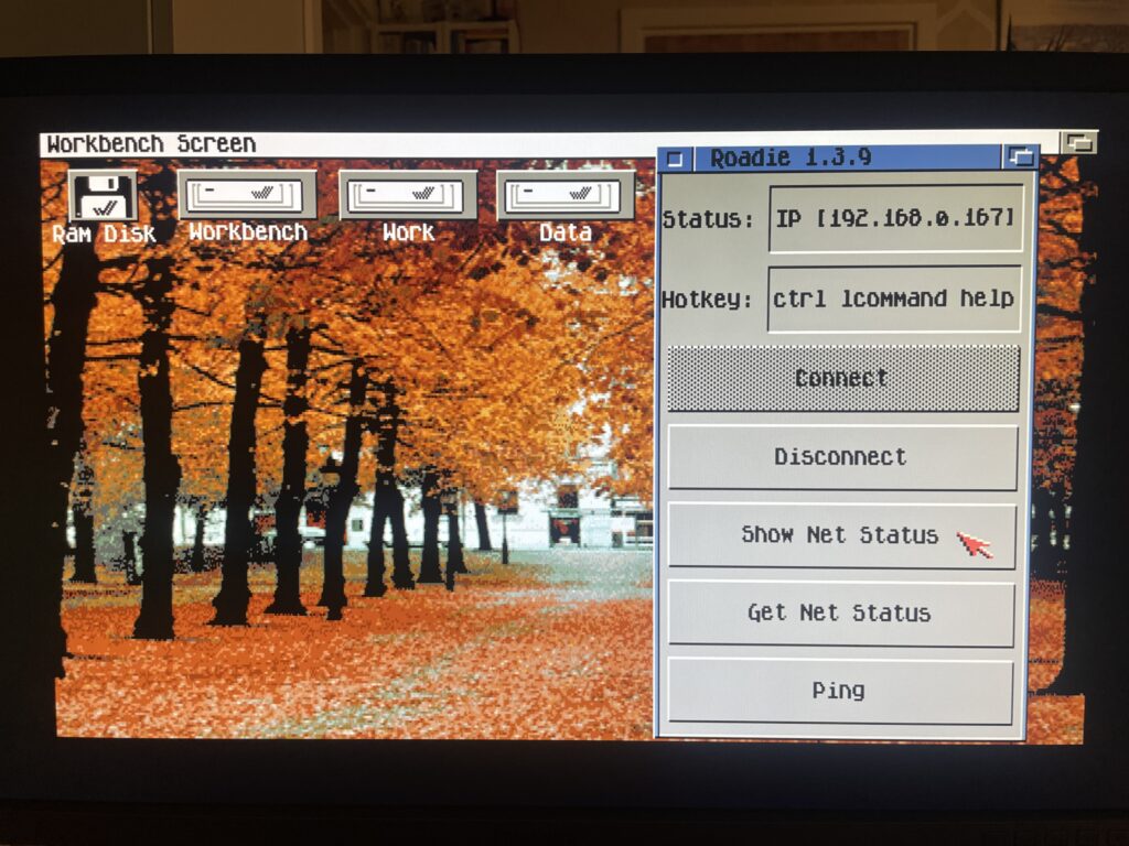
Roadie, a GUI for the TCP/IP stack Roadshow
Before I close off I also want to quickly introduce Roadie, it is a GUI for Roadshow you can find on Aminet. It has come in handy when testing the PicoWyfy and I think this one will go into the default toolbox on all my Amigas. Find Roadie on Aminet.
And here we are after a reboot of the Amiga 1200. There is no sign of it but my A1200 is connected to my wireless network at home!
Conclusion
I am very happy with the PicoWyfy, its a great addition to my A1200 and to be honest I would like to equip all my Amiga computers in the fleet with one or a card with similar functionality. Great work everyone involved in this project! Highly recommended!
Typically I like to use wired network, but as the years has passed I think wireless networking is perfectly fine. Even for non mobile computers.
I dont run WIFI on my main desktop workstation, but for everything else, why not, one less ugly Cat 6 cable to pull out everytime one wants to hook up something to the internet.
The reason for wanting to connect an Amiga to the internet or a LAN is primary just to move files to the Amiga. But I have some future plans of having all files centralized on a main server and then sync that share with my Amigas. That way I have multiple backups of my Data folder on all my Amigas while I have a central location that I primary update.
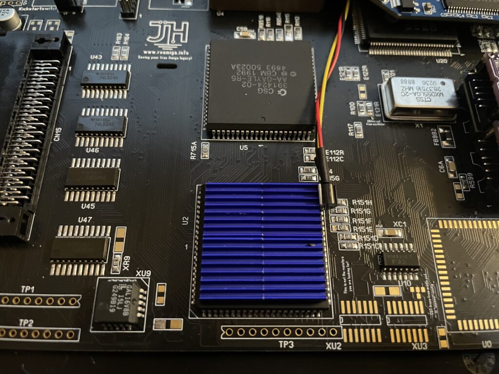
Alice is the graphics chip in the Amiga 1200 and Amiga 4000. It runs hot. The main board acts as a heatsink for the chip so it is not really nesesarry to add a heatsink to the chip. But to help it out with some additional cooling anyways I placed four 3 mm tall heatsinks on Alice (on thermal tape). It still hits 50 degrees, but if I remember correctly, it runs slightly cooler.
Solas installed in my ReAmiga 1200, it is the blue board to the left of the floppy drive
I have recently been playing around with the highly sought after Solas. The Solas is an RGB LED controller for the Amiga, it also has some other interesting functions. Solas connects to the Amiga on the clock port and can control two LED strips. Solas has also the ability to control fan speed and measure temps. It is also a clock port multiplier!
While I am not very interested in RGB lightning in computers typically the difference here is that the RGB lights can react to the sound the Amiga is putting out. When playing a module you can see the LED strip jumping to the beat of the music. How nice!
I enjoy playing modules on the Amiga and all kind of graphical visualizers for module players are all kinds of awesome. The more the better – I have been thinking of hooking up external VU meters for many years but to have them integrated into the Amiga is much better!
Before we contionue – If you are interested in the Solas board I highly suggest visiting the official Amiga Solas website and ordering one now! These days, good things come in small batches in the world of Amiga and if you dont hop on the train before it has left the station, sometimes it never comes back.
Building the Solas LED controller
I like building hardware myself so I asked if I could get the Solas as a kit, which I could. I also got a second Solas already built, it is a long story why and I wont write it down here to bore anyone. Lets just say, resistors can go bad sometimes and sometimes it can be good to have an oscilloscope in your toolbox (I dont have one).
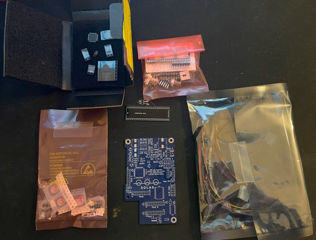
Here is the Solas in kit form. A nice mix of through hole parts and surface mount components. Also note all the cables for the temp sensors and power cable.
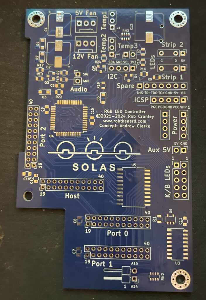
Front side of Solas Amiga RGB LED controller PCB
The square space if for the chip that needs to be programmed. You can also see all through holes for pin headers and clock ports. The manual comes in really handy here in understanding how everything is tied together.
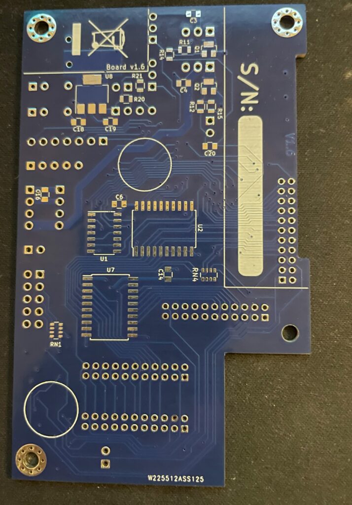
Backside of Solas PCBPrograming the PIC microchip on the Solas
I thought I could program the Solas with my RPI. I have successfully managed to program many projects that uses Xilinx CPLDs with the RPI but was not successful in this case. So I got a cheap Pickit programmer. It is not visible in the image above though but worked fine – setting up the Pickit programmer with the correct software and settings was a nightmare though.
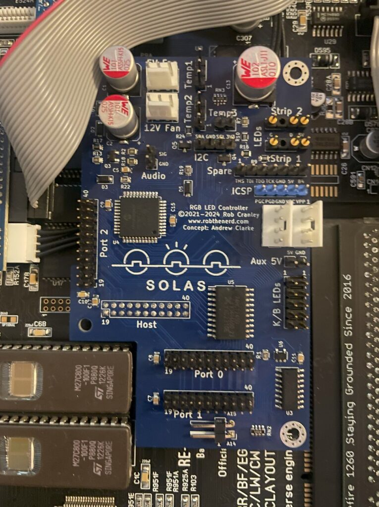
So here is the little PCB finally fully built and installed in the A1200. As it connects to the clock port it is very important that it is fitted correctly on the bottom pins. If you use a cable and mount it wrong way, expect card to break. Why would you mount it on a cable? Say you have an Amiga 1200 tower, it might be better to mount it on a cable so that a Zorro 2 or Mediator backplane can be fitted in the tower. Mounting Solas on a cable is also relevant if you have a clock port in a big box Amiga through a Zorro card.
Next steps, connecting all the cables to Solas and Amiga 1200
Installing and adding cables to Solas in an Amiga 1200
The manual is very good at explaining how you hook up all the cables, it is slightly confusing doing this without consulting the manual trying to figure it out yourself so in this case the manual is a must read (lol). In the image above, there is a small PCB that sits under the upper Kickstart chip and hooks up to the Solas with two wires. That is for activating the other clock ports on the Solas (IIRC).
How to connect sound output into Solas on a ReAmiga 1200?
Pin header for mono sound input to the Solas on the ReAmiga 1200 v1.5
Since I was using a ReAmiga 1200 and not a Commodore made Amiga 1200 there is one difference that needs to be taken care of. On a genuine Commodore Amiga 1200, you can pick up mono sound from the modulator. But the ReAmiga 1200 does not have a RF modulator and is missing the mono output there. On later ReAmiga 1200 (I have v 1.5) there is space for a pin header close to the keyboard MPU chip where you can pick up mono sound (see image above where I have soldered on one pin header to the motherboard). Also note the place above and to the right of the pin header where you have to add a 10uf ceramic capacitor. I have not added the capacitor on the picture above.
To get the Solas to react to sound input I also had to place a 10k resistor inline with the cable connected to the pin header and to the Solas board. After that, everything worked fine!
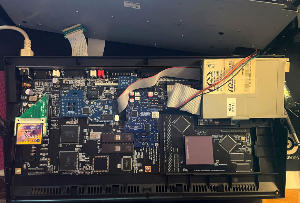
ReAmiga 1200 with Solas installed
So here you can the full setup. Unfortunately it looks a bit messy with the Indivision, CF adapter and all the cables all over the place. It is possible to clean it up a bit, but for testing purposes this was fine. You can also see where I placed the RGB LED strip. I ended up super gluing the LED strip to the case because the sticky backside was not sticky enough. I routed the cable from the Indivision MK3 under the Solas board, made it look much cleaner and works fine.
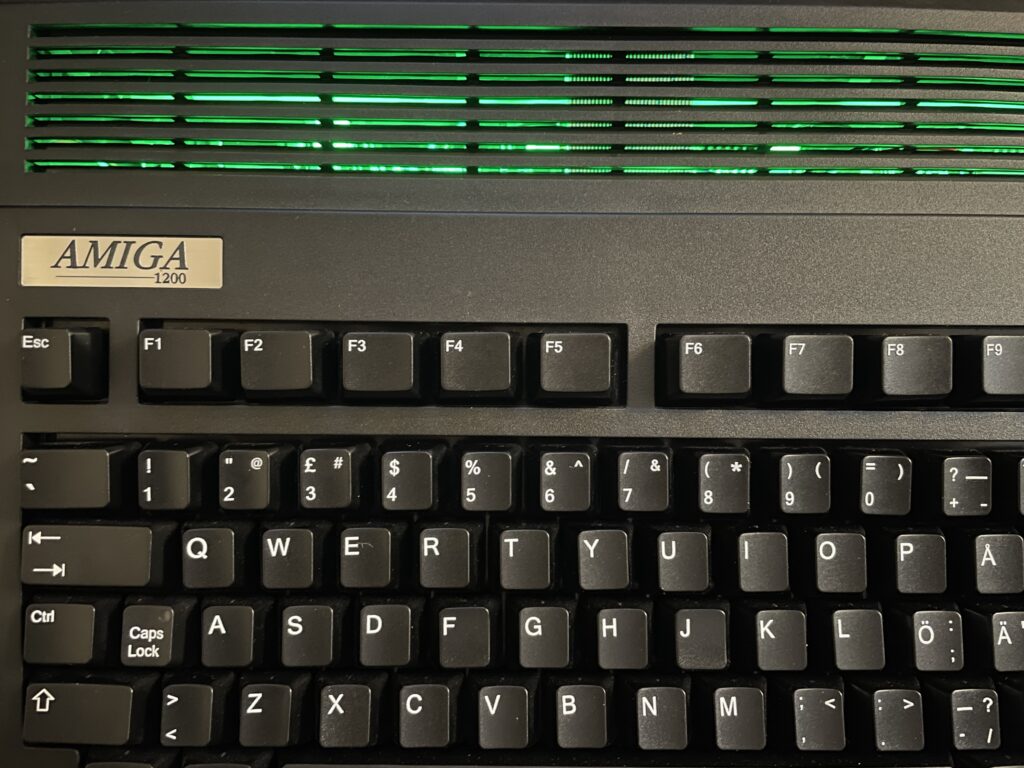
RGB LED strip is mounted to the underside of the upper Amiga 1200 case
Closeup of where the RGB LED strip is mounted. Even though it is mounted upside down in a solid black case it works fine and you can clearly see the light the LEDs are emitting when they are lit.
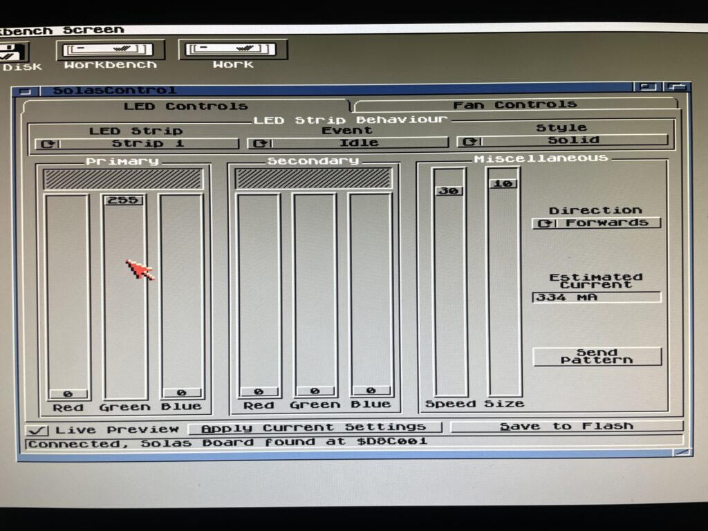
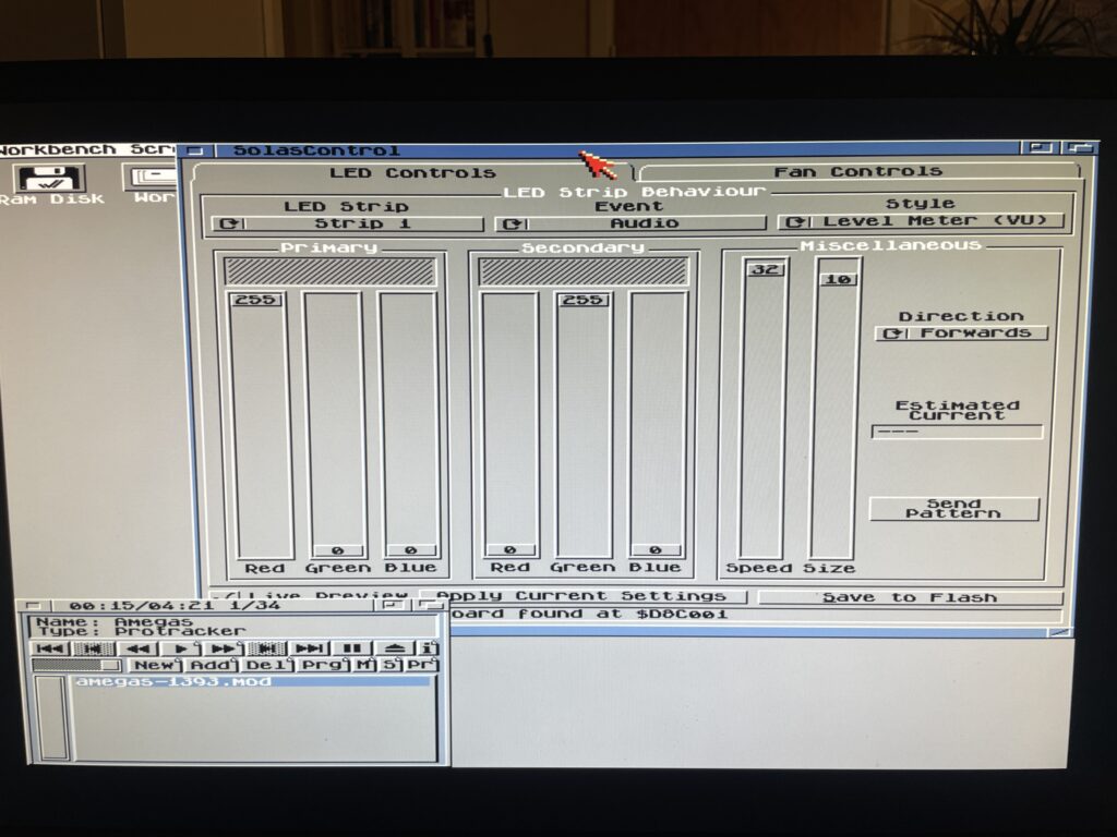
SolasControl – Software to control Solas
Use SolasControl to configure the Solas board in the Amiga
Solas comes with a great MUI based program that lets you configure Solas. The way this works is that you configure Solas, then you save your settings to the Flash on the Solas. That means that Solas will work with software that fully takes control of the Amiga.
SolasControl is an easy to use program, in the image above I have configured Solas to show a solid green light when the Amiga 1200 is idle. It looks like this:
Solas configured to show a solid green color when the A1200 is idle
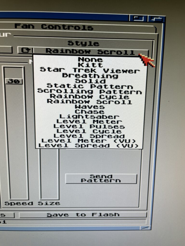
Solas styles and events
As you can see on the image of SolasControl, you can set the level of brightness for the LED and in the highest strength the LEDs are very bright. I usually do not run the LEDs at the highest brightness.
Styles you can chose from in SolasControl
A static color is a bit boring. There are many styles you can chose from, my favorite is a rainbow scroll with a low brightness setting when idle. See the video below to see an example of it where I chosed blue and red as colors for the scroll.
Speed, colors, brightness and size depending on style chosed can be configured to ones preferences.
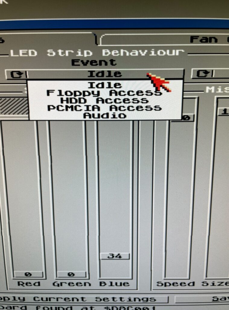
There are in total five types you can set the Solas to react to, Idle, Floppy access, HDD access, PCMCIA access and Audio. Idle just means when Solas is idle (when the other types are not active). Audio is when there is audio output and floppy/HDD and PCMCIA is when there are activity on these devices.
I like to run Star Trek Viewer for HDD Access, its a nice effect when accessing the HDD. I also as said before run Rainbow Scroll with a low brightness setting when idle. And finally, the pièce de résistance, audio. I like Level Meter (VU) for audio!
RGB LEDs reacting to Amiga sound
Playing a module in HippoPlayer on the A1200 and watching the RGB LEDs react to sound
I want to point out that I usually run a little more fancy Workbench (even on this non GFX board AGA only Amiga 1200 WB 3.1), but in this case I toned it down a lot to clarify images.
In the image above I play a module in HippoPlayer, I have also configured Solas to show Level Meter when sound is playing. And I think it looks fabulous!
This is actually why I think the Solas is so exciting since I wanted a hardware device like this for the Amiga for a long time. I remember looking for similar types of hardware on AliExpress more than 15 years ago that could be added to a 5.25 bracket back when I had an Amiga 1200 tower. But this is so much better since it can be configured on the Amiga!
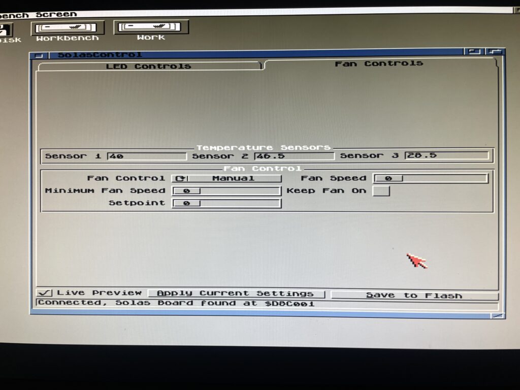
What about controlling fans and measuring temps with the Solas?
Solas comes with two sensors you can place where you want to. I placed one on my Indivision (as it runs very hot) and the other on Alice as it also runs hot. It is possible to add a cable between TerribleFire 1260 and Solas to measure 060 temps, but I have not had time to do that yet, but thats on the todo list.
The fan control function is very interesting particularly if using the Solas in a big box Amiga with many Zorro cards and hot CPUs. I think this is a nice alternative to CPLDIcy.
Usefulness of more than one clock port?
There are exciting developments in the Amiga hardware world where some users have created clock port based WIFI cards for the Amiga. There are sound cards for the clock port and USB cards. So having more than one clock port can actually be usefull – who knows what type of hardware will be released for it in the future. Having a couple extra feels great for the future.
Solas and big box Amiga computers
It is possible to add a clock port to a big box Amiga with Zorro slots through an old Buddha card, ZORRO-IDE-LAN-CP card and many other cards. That makes it possible to run Solas in an A2000, A3000 or A4000.
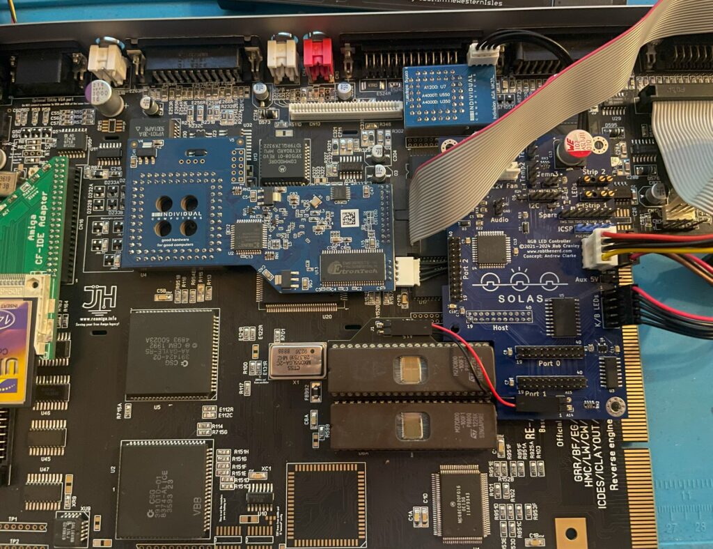
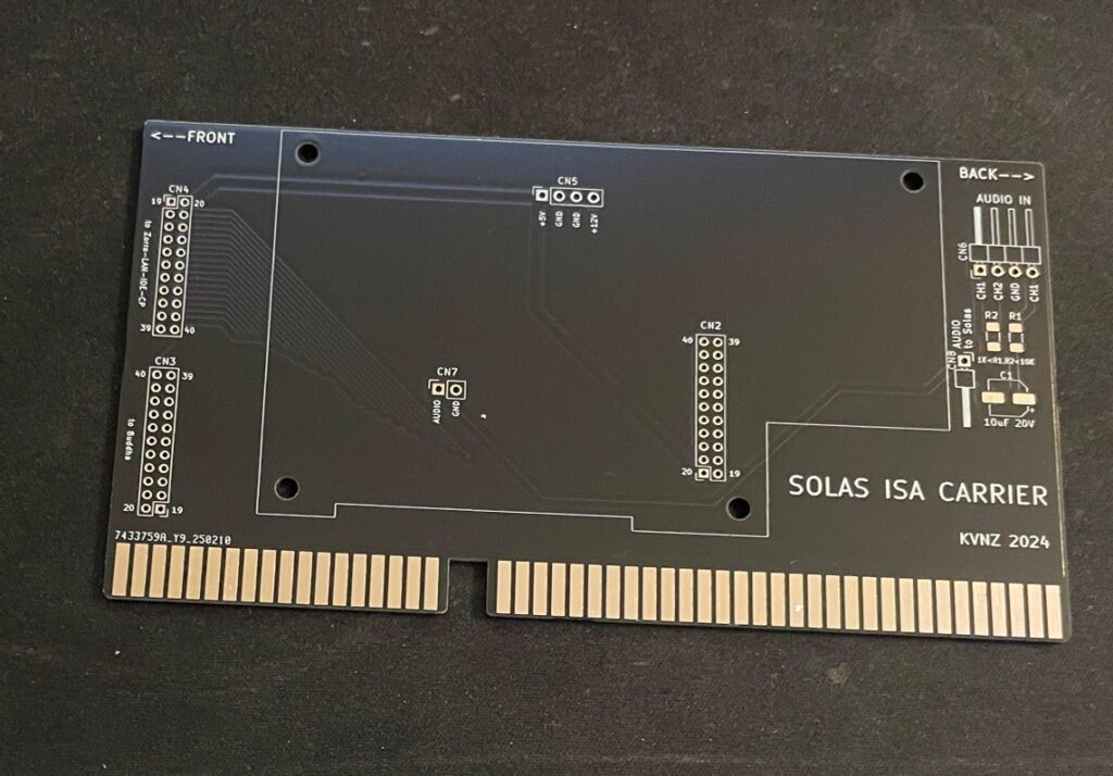
Solas ISA carrier
There is also this exciting ISA card that functions as a carrier for the Solas. As you probably already know, ISA slots in an Amiga are totally passive, meant to be used for PC bridgeboards or TBC cards. so the Solas ISA carrier only provides power to the Solas. It has some useful pin headers though.
Solas mounted on the ISA carrier
Mounting the Solas to the ISA carrier board needs a slightly modified Solas card. One also needs to figure out how to connect sound to the Solas. I figured out that I can take it from pin headers on the ZZ9000 graphics card I am running in my Amiga 4000TX.
How I got sound input into the Solas from the ZZ9000
So here is how I hooked up sound input from the ZZ9000 graphics card to the Solas. Unfortunately the picture is a bit grainy but you get the point, L/R goes into the Solas ISA carrier. Also, it is a temporary cable as only two wires are needed.
Here is how the Solas is connected to the clock port of the Zorro-LAN-IDE card
And here is how the Solas is connected to the clock port on the Zorro-LAN-IDE card.
Keep in mind though if you have maxed out your Amiga expansion slots (we are all Amiga snobs left in this hobby right?) this sandwich of the carrier card and the Solas can be difficult to fit as it takes up more height than a regular card – And even more height with the cables connected to it!
I should also show you the LED setup I am running, I am running two LED strips on the inner sides of the front of the case. It looks awesome when playing tunes.
Final thoughs
As you can probably tell, I have only positive things to say about Solas. Highly recommended! I also think the Solas board is one of the greatest hardware developments for the Amiga in recent years (together with PiStorm and open hardware such as BFG and TF series of cards). Great work everybody involved with it 👍
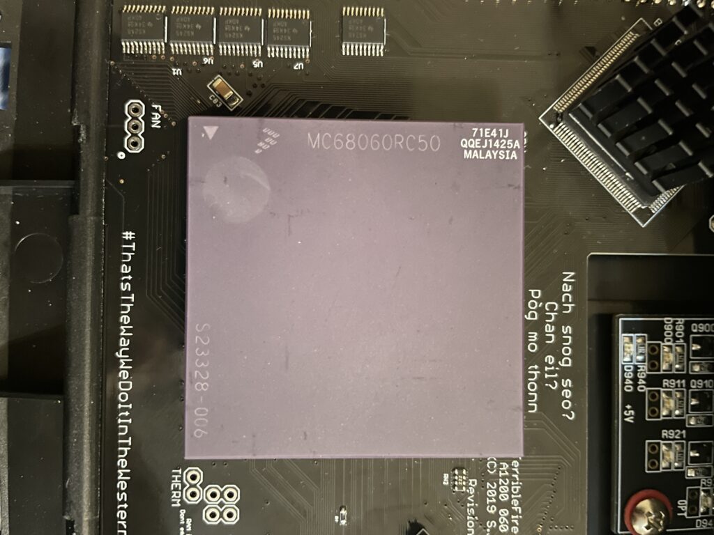
I bought a 68060 revision 6 (71E41J) recently for a very good price. The rev. 6 CPU can usually do a really good overclock, often reaching 100MHz or more, which makes them very sought after and sometimes fakes are offered as the genuine version of the CPU. As I was already running an 060 in my Amiga 1200 I was not sure if it was worth swapping CPUs to gain more megaherts. The rev. 5 68060 I was running could do a 66MHz overclock but ran very hot. And a 50MHz 060 is not a slow CPU (in the world of Amiga).
Swapping 68060 CPUs in my Amiga 1200
I decided to swap CPUs because I wanted to test performance of an Amiga without a graphics card but with a fast CPU and high resolutions (like HighGFX and highres laced). Luckily removing the CPU was not a difficult task, prying on the corners of the socket it was out in less than 5 minutes ready to go into another one of my systems. Once the rev. 6 CPU was inserted into the Terrible Fire 1260 I was eager to do a test. Sure enough, it did not complain anything running at 100MHz!! (keep in mind I had a heatsink on the CPU when doing tests). Next time I will try 106MHz!!
Is there actually a noticeable difference between a 50 and a 100 MHz 68060?
Would I be able to detect any difference between a 50MHz 060 and a 100MHz 060 or would it only be noticeable in a benchmark program?
I was not too sure – When I had overclocked my 060 in my Amiga 4000TX from 50 to 100MHz I could feel that icons loaded faster, drawers just popped up, Workbench was just smoother and more responsive. But I was not sure if it was my imagination or reality.
With that said, I was surprised that my 100% non scientific mean of measuring the difference between a 50 and a 100MHz CPU in the following AGA Amiga Workbench screenmodes highres, highres laced, HighGFX @ 1024×768 (all screen modes in 64 colors) proved that there really was a difference!
Workbench had become even faster and more responsive. Running 3.1 with the stock Commodore 4 color icons, icons did not load anymore, they just popped up, almost all at once, drawers opened up instantly. The system speed by at such a high rate I had only witnessed something like this in WinUAE. What an amazing experience!
I changed background colors to 256 colors and could sense little to no slowdown from a 64 color screenmode. Sure, I have to test this more, but the early results are great, this is what base level Amiga should be like! Lets bring on 200MHz 060 (lets crowd fund it lol).
Cooling problems
Before I permanently run this computer at 100MHz I have to figure out a good cooling solution for the CPU. This rev.6 68060 runs cooler than the old rev. 5 I had in it before. But overclocking it makes it run slightly hotter. I suspect its above 50 degrees but not more than 60. I have some ideas on how to cool it down but will have to sleep on the ideas a little more before I pull the trigger on the stuff I need to build one..
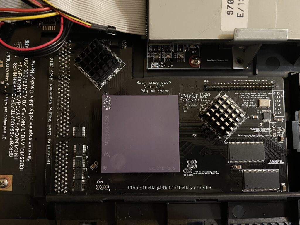
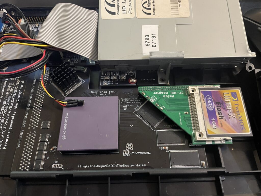
I have a Terrible Fire TF1260 in my Amiga 1200. I used to have an Apollo 1240 upgraded to 060 in it and was very happy with that card (despise what other said about the card, it was very stable for me). Time marches on though and the TF1260 started to look more and more impressive, so I built one last year. The TF1260 supports overclocking by software. One comment I read was that the chances of a good overclock improved if you put heatsinks on the two CPLD chips.
Keep in mind that I had a heatsink on the 060 when doing overclocking tests. But the space between the 060 and keyboard is so tight it was very difficult finding a heatsink in my stash that would fit with the keyboard installed. I have actually not solved this yet, thus I just focused on the CPLDs and will try to solve the 060 heatsink some other day, until then it will run at 50Mhz.
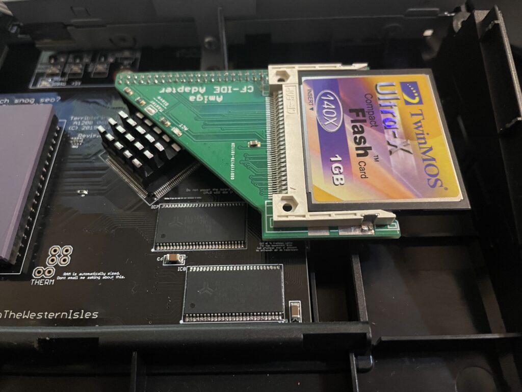
The problem with the CPLD cooler is that the right CPLD need a short heatsink if you want to run a compact flash adapter over it. As you can get an impressive speed boost for the CF card by using the IDE port on the TF1260 this was off course something I would need to consider.
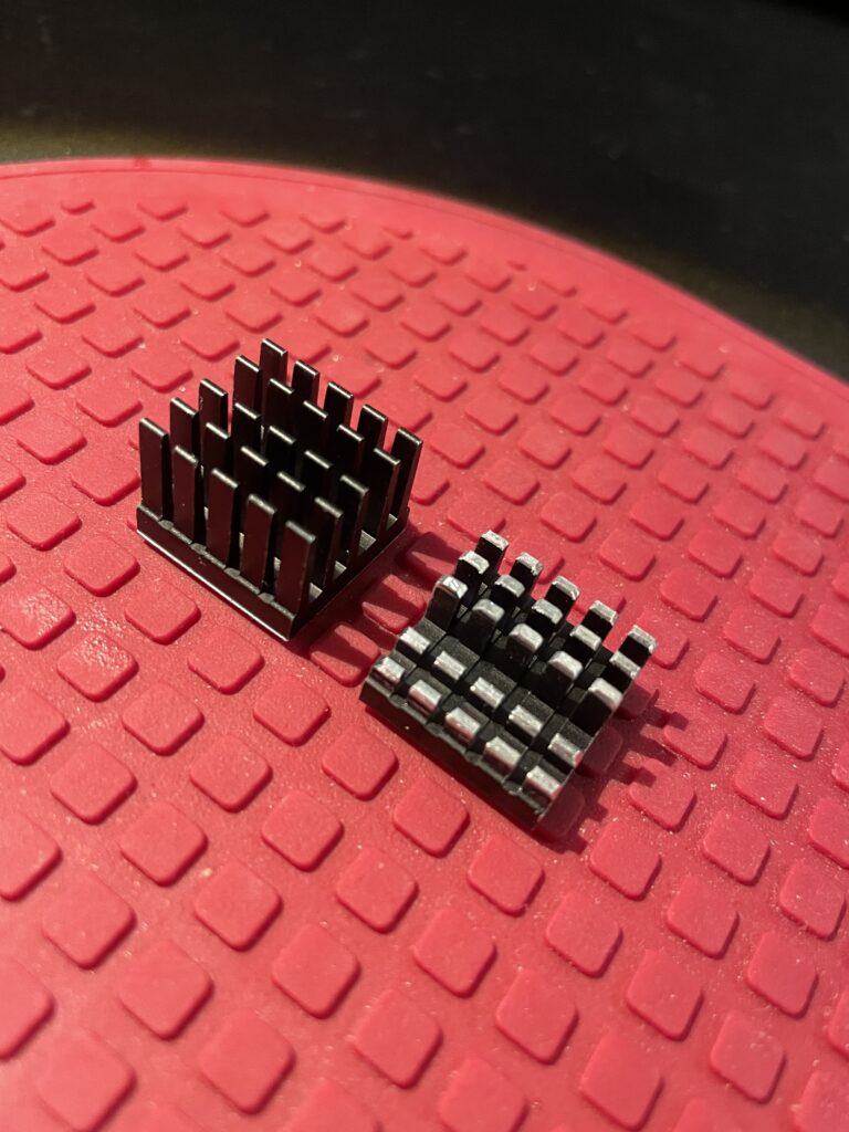
I had ordered these 18x18x20mm heatsinks for this exact CPLD before. The left one is the original form and the right one is the heatsink cut down and modified. I dont like to do fabricating as it gets so messy and difficult to get good results with hand tools. I will probably order a new heatsink in the correct height in the future.
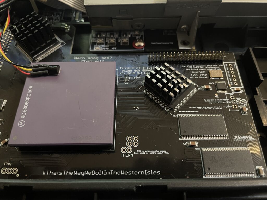
Here I am test fitting the heatsink.
And here it is secured to the chip. I use a thermal pad from AlphaCool that I cut to fit myself. The thermal pad from AlphaCool is somewhat thicker than what you usually get when you order heatsinks from Aliexpress. The thicknes is 0.5 mm, the thermal pad is also softer and more gooier than regular flat thermal pad. Once secured with the AlphaCool thermal tape, these pads wont go anywhere, they are secured very firmly. I highly recommend these AlphaCool thermal tape and would use them even on the 060 with a large heatsink without no problem or worry that the heatsink would fall off (even if mounted vertical!)
So here we are, everything fits now. But to use the IDE port on the TF1260 I need to burn a custom Kickstart with ehide.device, more on that when I will get to it.
And about finding a solution for cooling down the 060? I have not got a clue, I will probably need to cut down a thin copper plate and place a heatsink on it offsett from the CPU. Not ideal, but better than nothing. A small heatpipe cooler leading heat to fins over the top of the cards close to the floppy drive would be ideal, but prototyping a cooler like that would take weeks and lots of money. I will see what I will come up with.