I have worked on some small things here or there on my Amiga computers. Here are some noteworthy things that has kept me busy.
Installation of an 2.5″ angled CF adapter in my backup A1200

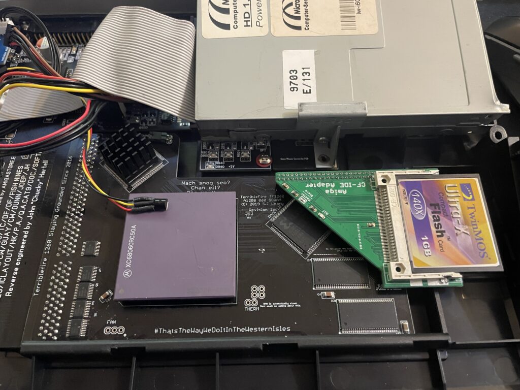
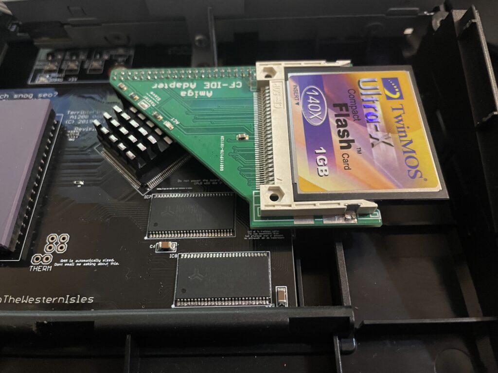
I found angled 2.5″ CF adapters on AliExpress. I have been looking for these for quite some time. They can not work if you have an Indivision AGA in your A1200 but if you do not have one they offer a great reliable way of running an internal compact flash drive in your Amiga 1200. There was only one problem:

They came with one pin blocked. I used a small drill to drill into the blocked pin and realised that it was only the top layer that was blocked. Next step: try it out in my backup A1200.

My backup A1200 has 3.1 Kickstart roms so I had to upgrade the Kickstarts before trying an Workbench 3.2 installation. So the next step was to flash some roms with AmigaOS 3.2.

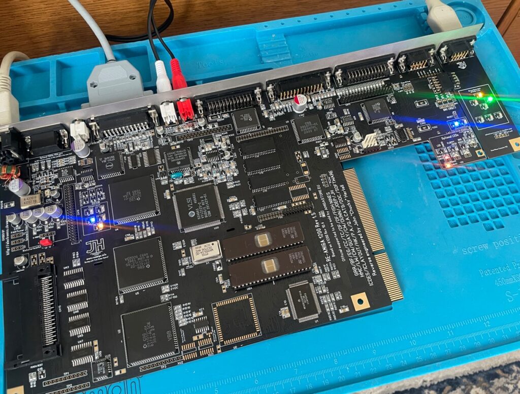
Here are the FlashROMs. I decided to flash DiagROM and Kickstart to them as they can hold two ROM images. It is very handy to have DiagROM availble if needed.

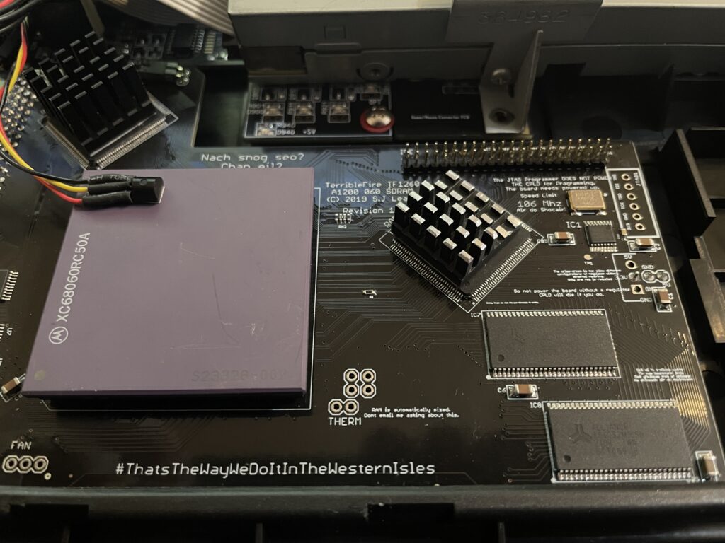
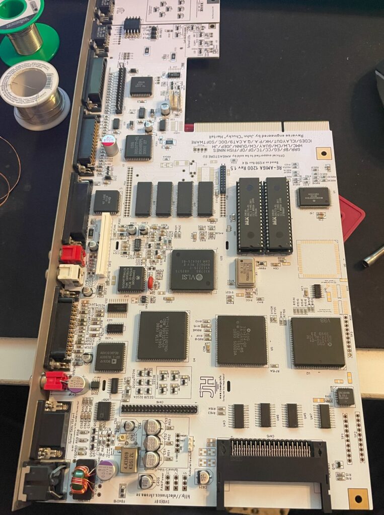
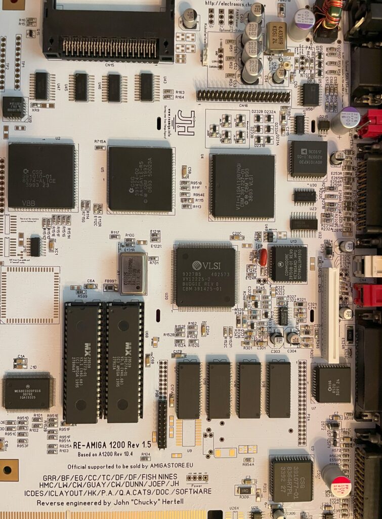
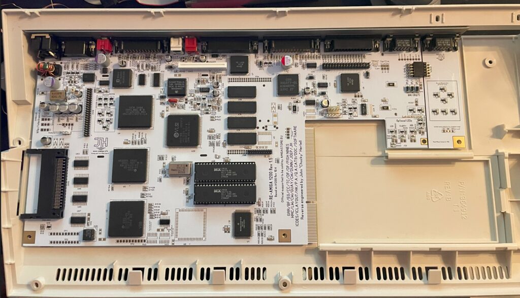
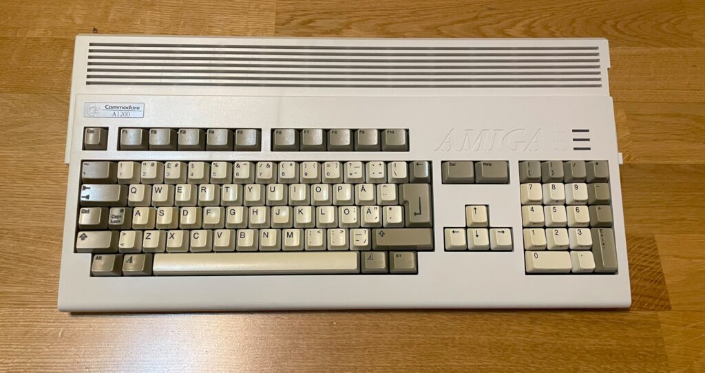
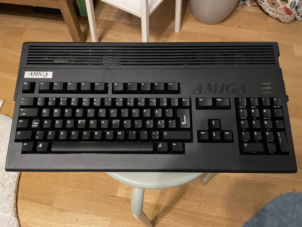
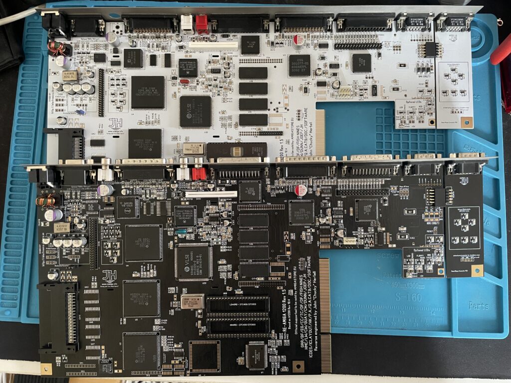
My backup Amiga 1200 looks like a regular A1200 on the outside but inside it is a white ReAmiga 1200 that I built a couple of years ago.

Here the FlashROMs installed. But it failed to boot into the Kickstart screen, DiagROM worked though. So out came the T48 programmer and FlashROM adapter again. It was impossible to flash the FlashROM again. After 30 minutes of fail checking I realized that I used the wrong USB-A cable for the T48. After swapping cables the correct ROM image was flashed and everything worked.

The ReAmiga 1200 has a nice Kickstart switch feature that you can enable. If enabled you can chose between two different ROM images through a jumper. If you do this with a FlashROM you do not need to jumper the FlashROM. As you can see, I never bothered to solder on the fan headers.

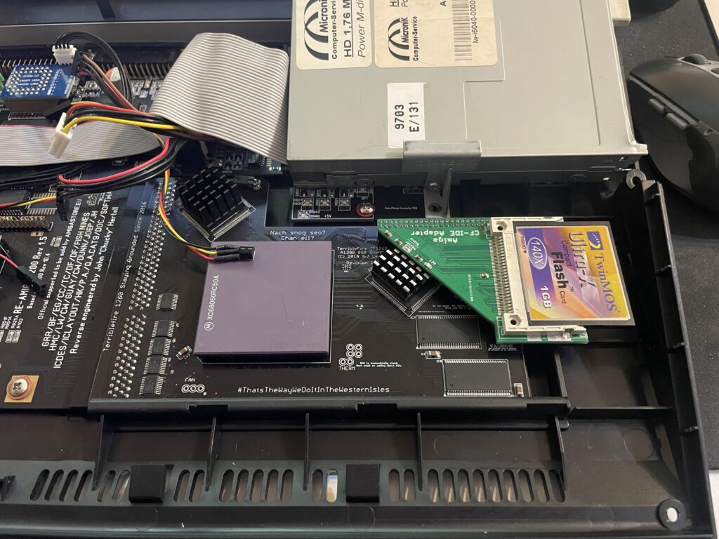
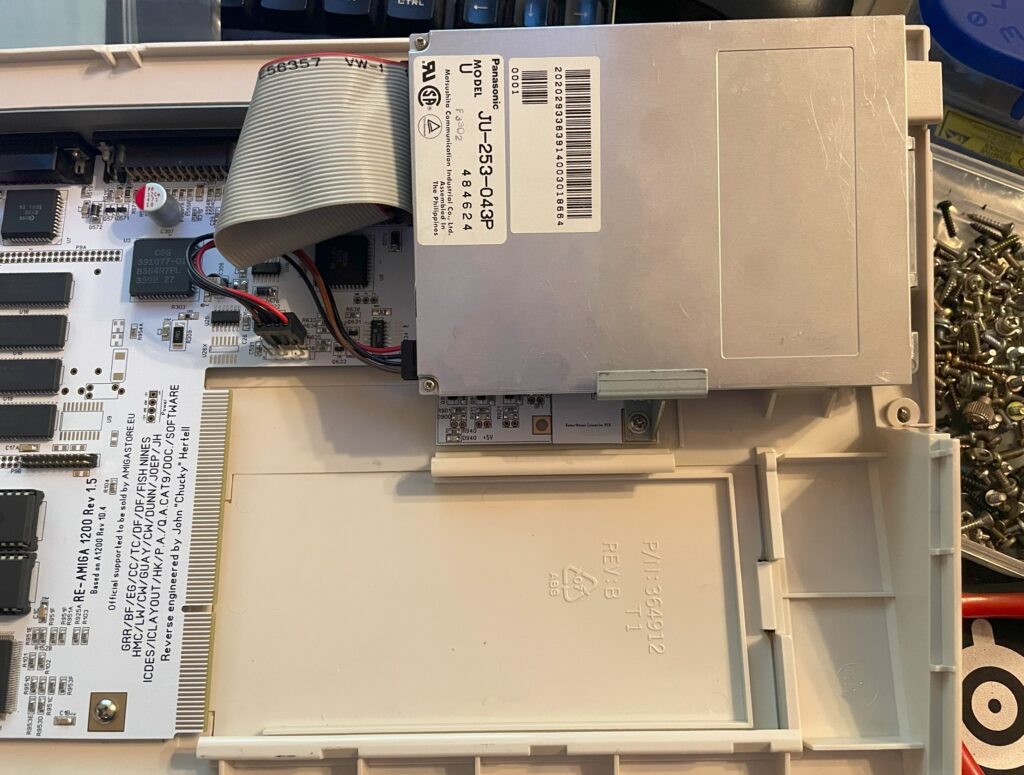
Here is the CF adapter mounted on the internal 2.5″ port of the ReAmiga 1200. Booting off of a WB 3.2 installation it worked fine.

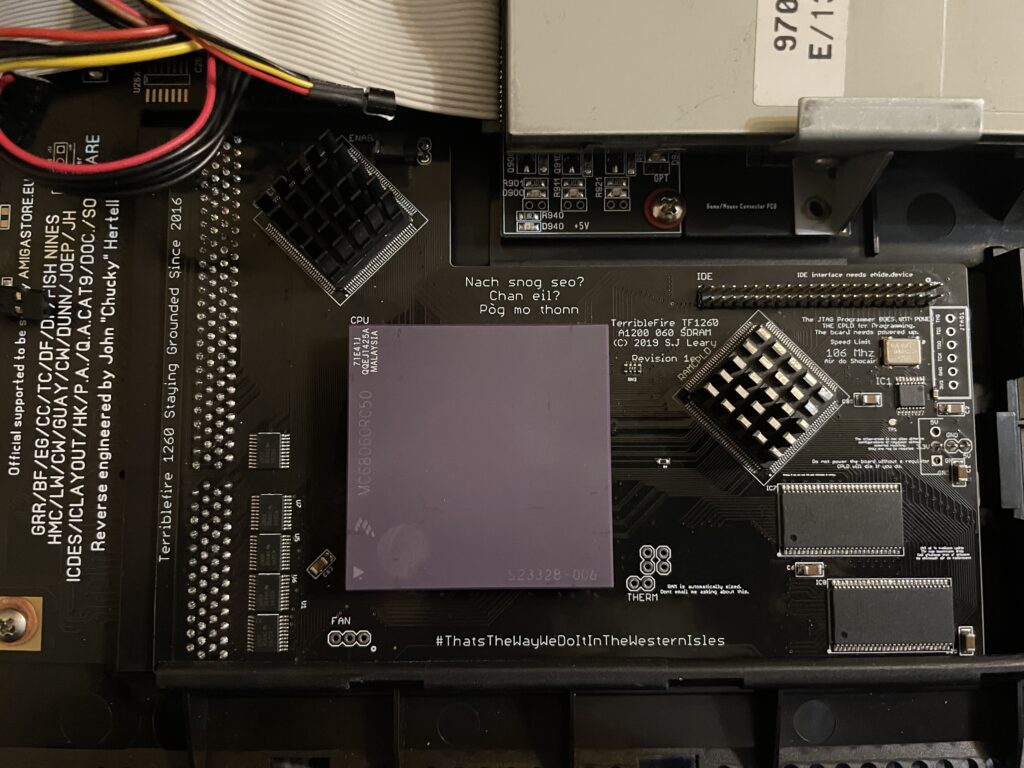
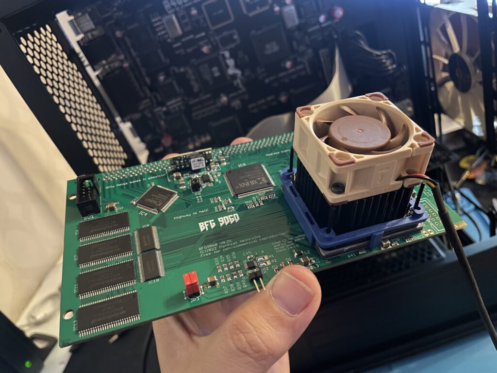
Making the ReA4091 work with a BFG9060 clocked at 100 MHz
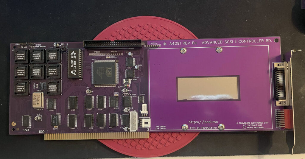
I had problem with my ReA4091 SCSI card when running my BFG9060 68060 turbo card at 100 MHz. The Amiga 4000TX worked fine if the BFG was clocked at 50 MHz but at 100 MHz the system refused to run stable giving me filesystems error instantly in Workbench.
This is not a new problem as many other has had it. But at the same time, many have gotten A4091 and a BFG with a 060 clocked at 100MHz working without trouble.
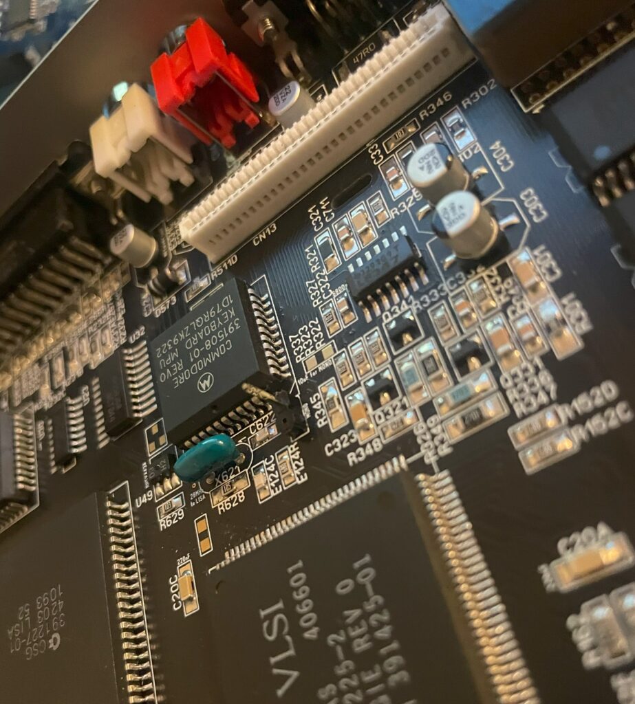
I got a heads up about a thread on github discussing possible solutions to this problem. You can find it here. One suggestion there is to reprogram U305 with the file from here.
Apparently this fixed the problem for the user who suggested it on github with a drawback of 10% less SCSI performance.
I did not have anything to lose so I decided to give it a go by flashing the little PLCC chip with the file suggested. To my surprise it actually made my hardware setup stable again at 100 MHz! Now that I have put in a few hours in my system I can confirm that it runs stable (and now more than 6 months later I can confirm that it has been working great).
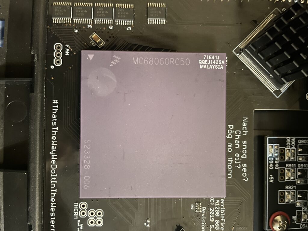
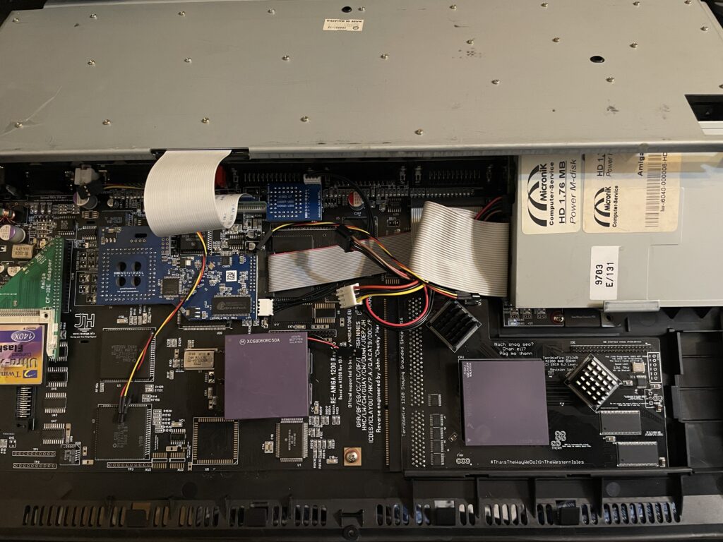
This particular build consists of an A4000TX, BFG9060 with a rev.6 68060, ReA4091 with a ZuluSCSI compact, there is also a ZZ9000 graphics board in the setup. It is my main setup.
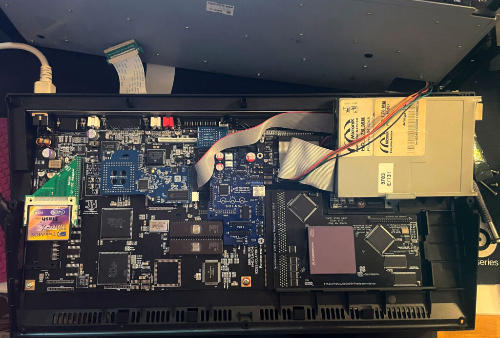
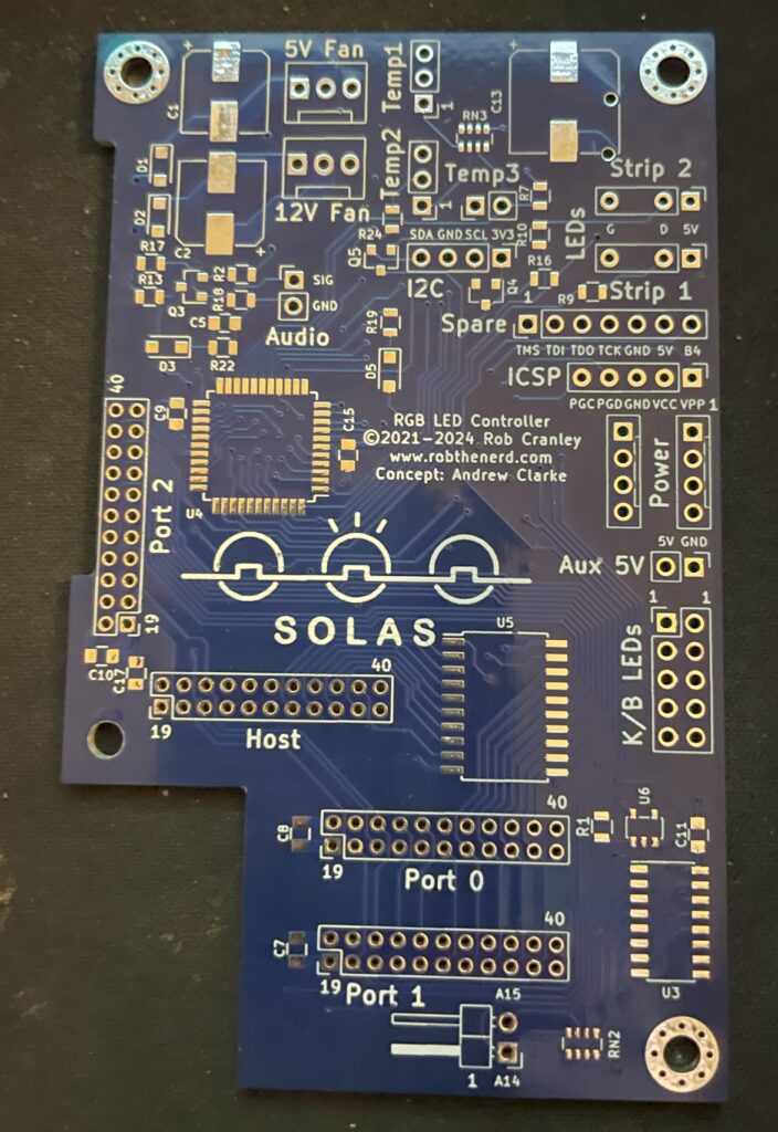
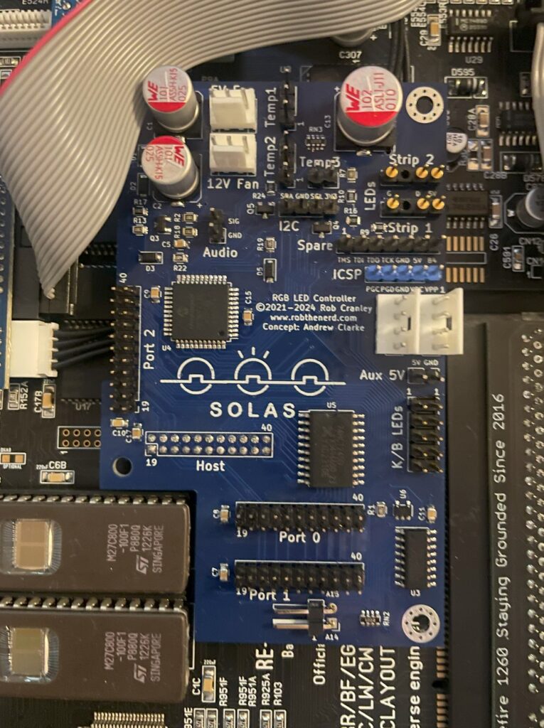
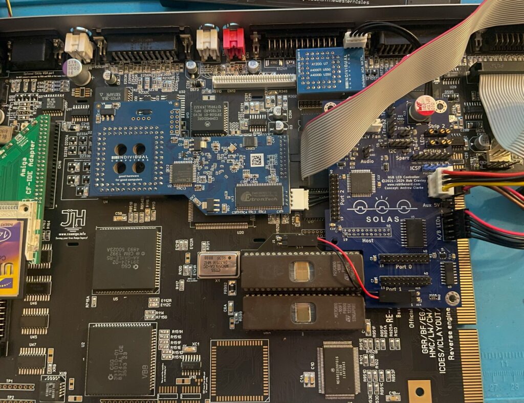
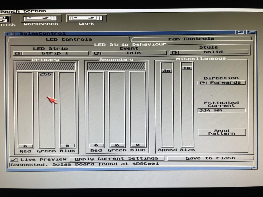
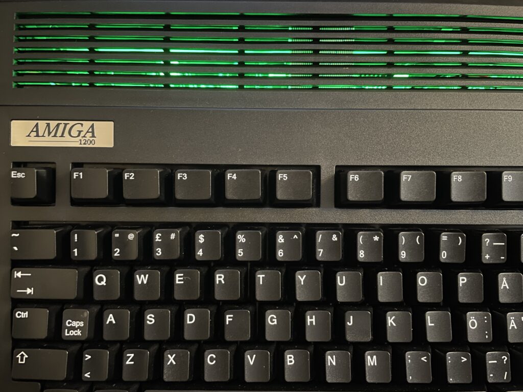
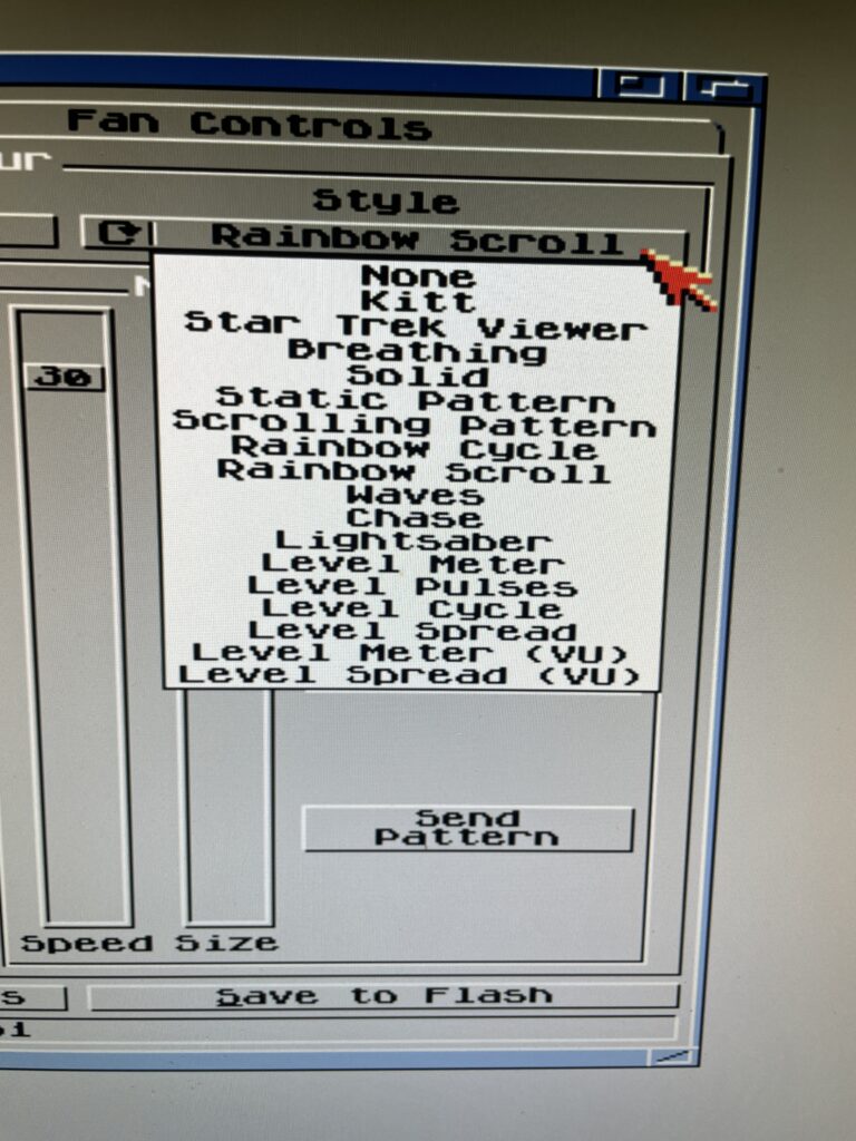
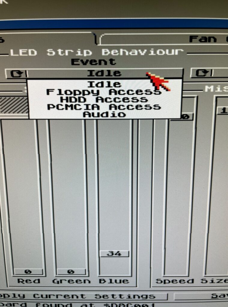
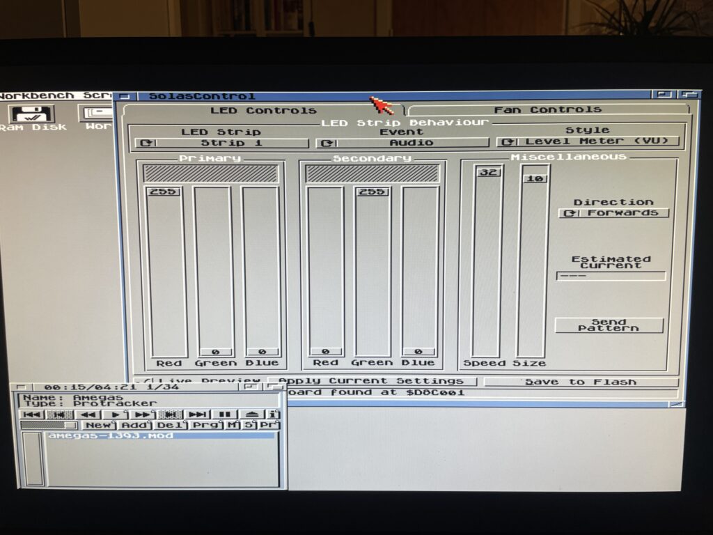
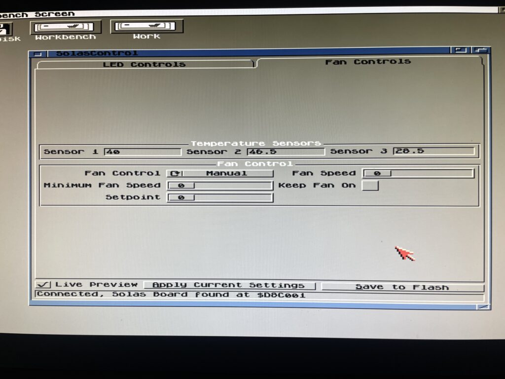
Solas + ISA board installation in my A4000TX

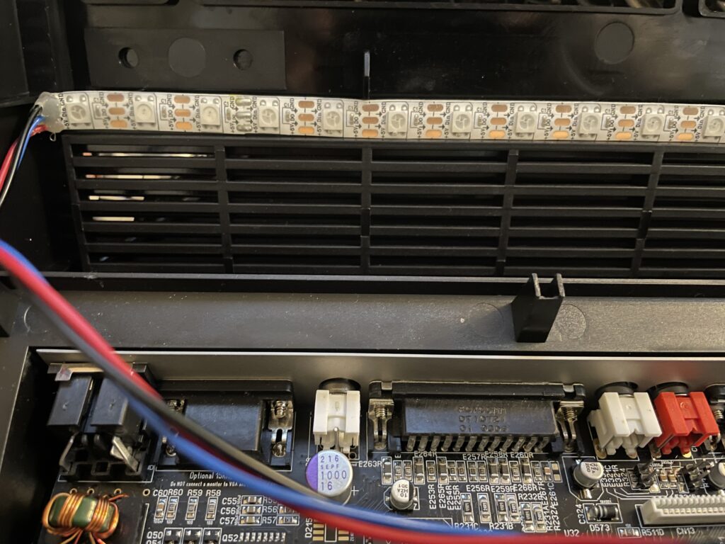
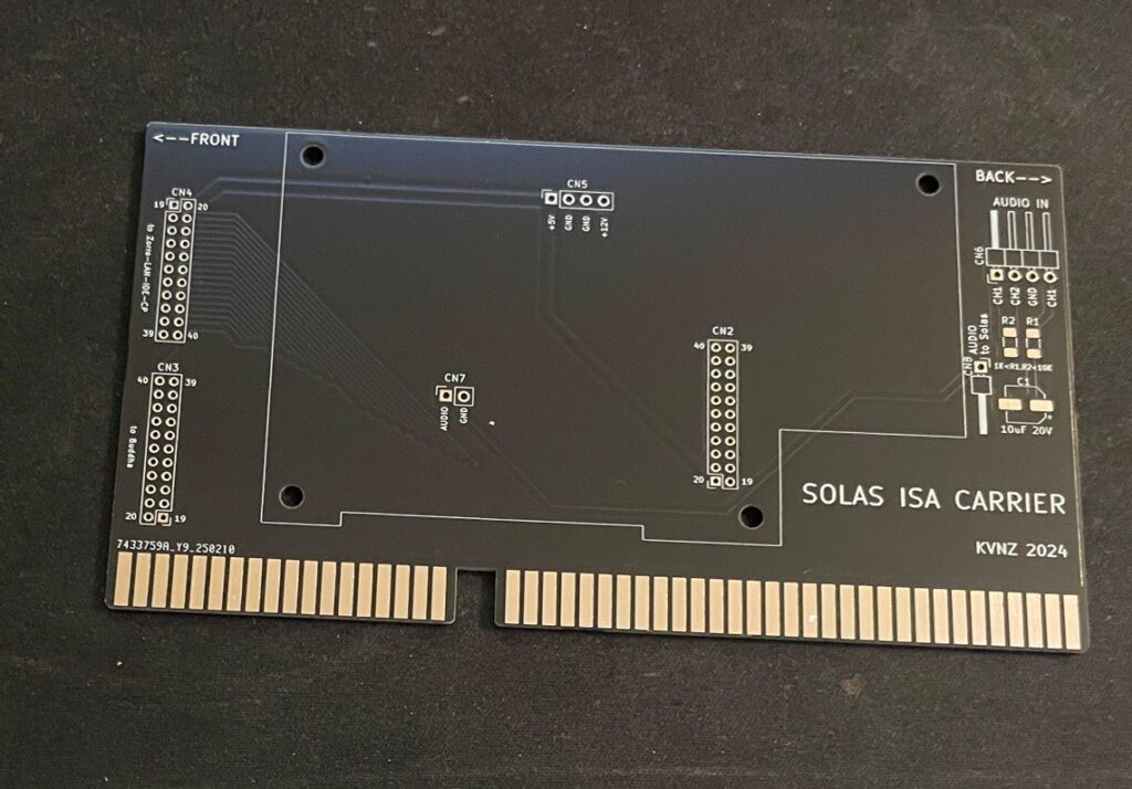
I have a Solas LED controller in my A4000TX, it is hooked up to an ISA carrier and is connected to the clock port on the Zorro-LAN-IDE card. It took a while to figure out how to connect them together and to get sound into the Solas. But after tinkering with it for a few hours it is working fine now.
The sandwich card of the Solas carrier and Solas is too thick though, making it difficult to run a full size Zorro card over it, I am thinking of soldering them together to decrease the height of the card sandwich. It could either be the greatest thing ever or the greatest disaster ever, I will need to flip a coin on how to proceed with this idea.
Second A2386SX board built and tested

I like to build things I like in pairs that is why I did not hesitate when I was given the opportunity to build a second A2386SX clone again. You can see some more pics in the previous link. I do not think I will build more of these boards as they have given me a tough time both in getting them working and in sourcing components for them.
A4000T AT case mod

I did not hesitate to jump on the train when an A4000T replica PCB was offered for sale on Amibay a few years ago. Building it was a lot of fun and also fascinating. The A4000T is after all the final official 68k Amiga computer released.
I was too naive expecting a case to show up by itself. Now I realize it might never show up so I decided to look for solutions. There are ATX options but I wanted to try an old AT case first.
The universe was aligned with my third eye and suddenly an AT case manifested itself on a local trading place. But the struggle is real, nothing comes without pain and struggle. The A4000T motherboard is huge, it wont fit this case without some cut fingers on old sharp PC case sheet metal edges and serious case modding. And I hate hardcore sheet metal case modding and cutting my fingers on old shitty PC cases.

But once modded though, the 5.25 bays the case has wont be usable any more. It wont be able to take an AT or ATX PSU anymore either. But hey, when it is fully modded, at least I got a case for the A4000T where the daughter boards line up perfectly on the back of the case. I just need to figure out how to mod this case in the simplest way possible.