Building an Amiga 4000T Replica Into a PC AT Tower Case

I built an Amiga 4000T motherboard replica two years ago. It was a fun build and a great way of getting to know the A4000T model that I have had little experience with. Naturally, when the PCB was offered for sale I jumped on the possibility to buy one even though I did not really have a master plan.

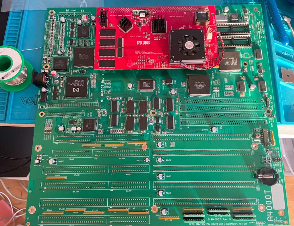
A freshly built Amiga 4000T replica motherboard

An example of this no-plan setup was that I had no idea what case I would use for it. Though I assumed the situation would fix itself either one way or another in the future (as it usually does).

The A4000T is an interesting Amiga. It is the last C= Amiga computer and it is different from other Amiga models in certain areas.

For example Commodore used daughterboards for various functions and offered it in a really cool full tower that later was replaced with another style (even more cool looking) full tower by Amiga Technologies.

Difference between Amiga 4000D and Amiga 4000T

Compared to an Amiga 4000D the difference between A4000T and A4000D are:

Amiga 4000DAmiga 4000T
CaseDesktop caseFull tower case
Form factorBaby-AT (like)AT
SCSINo SCSI on boardSCSI2 on board
Zorro slots4 Zorro slots5 Zorro slots
Video slots1 video slot2 video slots
ISA slots3 ISA slots4 ISA slots
Internal speakerNoYes
DaughterboardZorro/ISA/VSSound/IO/Ports

While the A4000D is sort of Baby-AT in its form factor it does not follow PC guidelines for the Baby-AT format as it has ports soldered to it on the back and i slightly larger.

Amiga 4000T compatible cases and finding the right case

The Amiga 4000T motherboard follows the AT standard and should fit large AT cases. It can also fit EATX (Extended ATX) cases with modifications.

Original Amiga Technologies Amiga 4000T case

When I was a teenager this was the coolest Amiga case ever -I think- but from todays perspective I think it has some problems.

  • First problem, it is a huge case and the space is not really optimized well, and even if it was optimized well I would not need that much drive bays these days.
  • Second problem, it is impossible to find one. Good luck finding one!

The Amiga Technologies A4000T case was actually just a regular PC case from Enlight. There are similar cases from Enlight that occasionally pop up on Ebay that can be used but if you want the original prepare to wait and save money for the rare occasion it shows up or hope that someone makes a replica.

AT cases

Can you use AT cases for the Amiga 4000T motherboard? Yes in some cases, depending on if the case has enough space for the motherboard. In the 90ies, there was both AT and Baby-AT cases.

The A4000T is AT, it is a larger size than Baby-AT. When I researched cases I found that many full size AT towers could fit the A4000T if you ditched the internal 3.5″ bay.

Most AT cases has the DB9 and DB25 cutouts at the back for the IO module and mounting holes for the motherboard should match.

ATX cases

Can you use a modern PC ATX case for the Amiga 4000T motherboard? Yes, with some modifications it is possible to use a standard PC EATX (extended ATX) case for the A4000T motherboard.

The A4000 is a huge motherboard so it wont fit shallower ATX cases. The case has to support EATX. EATX is wider than regular ATX.

There are a few problems with going the ATX route. But all of these can be fixed by modding the case.

  1. Some screw holes for the motherboard do not line up correctly in the case.
  2. There is no space for the IO module. To be able to access mouse, joystick, parallell and serial ports from the back you will need a special A4000T ATX I/O board that is available here (or wire up ports directly to the motherboard pin header).
  3. There is no space for the disk module to be accessed from the back of the case.

PC AT tower case for A4000T case mod

A classic PC AT computer case from the middle of the 90ies

As said above I did not really have any plans on what case to use but I found this old beige PC AT case on a local trading website and I instantly thought for myself, could the A4000T motherboard fit into that?!

I thought it looked small, but after spending an hour in Photoshop adding the A4000T motherboard on top of a side pic of it it in a separate layer I thought it could actually fit inside.

Believe it or not, I actually had an AMD K6 in exactly this case almost 30 years ago. Maybe it is the same case? What comes around goes around.

The case has three 5.25″ drive bays and one external 3.5″ drive bay and two internal 3.5″ drive bays. It also has space for a front 80 mm fan. As the case will be heavily modified I expected all of the drive bays to be non usable once the A4000T motherboard is fitted inside. The case also has this unnecesarry door that slides up and covers all the drive bays. I remember it was a major PITA BITD, but it sure makes the case look clean with the door closed.

DISCLAIMER

I want to point out, the aim of this project was to find a case for an Amiga 4000T replica motherboard. As such the goal was not to make a showstopper but an actually working setup that would enable the Amiga 4000T to be used regularly and reliably. It is not the most beautiful case in the world but for real world use this project makes the A4000T motherboard usable without hunting down an unobtainium or 1000+ euro case.

Could the PC AT case be converted to fit the A4000T?

The picture above shows the case with the cover removed. Cases do not look like this anymore, it was nostalgic to see a case like this again, though I prefer modern black cases.

The AT and Baby-AT form factors disapeared from the markets almost 30 years ago and was replaced by ATX. ATX gave us bigger cases until Mini-ITX became viable alternative. Some ITX cases are the same size as Baby-AT cases. I always wanted a BoXeR in a small Baby-AT case. That never happened though and after 30 years, I think it is fine and not something to get upset about anymore, there are so many badass alternatives these days that the BoXeR is just a faded, if not very cool, memory now, if all.

The case would need a lot of work to be able to fit the A4000T motherboard

This picture shows one of the problems the case had. There was simply no way of installing the large Amiga 4000T motherboard in the case without cutting off the 3.5″ drive bays and the horizontal support shelf under the PSU at the back of the case. The A4000T motherboard is simply too tall to fit otherwise.

The back of the case

The picture from the back of the AT case shows cutouts for DB9 and DB25 connectors. The IO daughterboard can simply be installed here, however some other modifications are needed, more on that later.

Also, take notice of the keyboard connector hole that lines up with the A4000T motherboard beautifully and the 7 slot card openings that lines up with the A4000T video slots, daughter boards and Zorro slots. Inside, the motherboard almost lines up with every hole inside.

That horizontal part has to be sawed off

Another look at the inner piece I had to cut off. I do not have access to power tools so I had to come up with a way of sawing it off with a metal saw.

I do not enjoy doing sheet metal work in my living room, often it turns out really bad and amateurish looking. But sometimes you have to be bold, I think this was such a time.

Modifying the PC AT case for the Amiga 4000T motherboard

Drilling out the rivets to be able to work on the case better

To be able to do the nesesarry modifications I used a hand powered drill -that I suspect is 100 years old- to drill out the rivets for the upper side plates. This drill has been with me through many Amiga case mods during the years, a lot of Amiga case mods, maybe too many Amiga case mods.

The side plates had to have the horizontal stability plate that sat under the PSU cut off. The internal 3.5″ drive bay was easy to remove as it was just riveted to the case and just had to have its rivets drilled out.

I did not take any picture of sawing pieces off but imagine spending four evenings with a metal saw blade like a mad man. Whatever it takes.

First test fit of the Amiga 4000T moterboard in the PC AT case

I could finally do a test fit of the motherboard when the pieces that blocked the motherboard from being installed in the case was sawed off.

I was really surprised to find out that there was space left to use the upper 5.25″ drive bay even after the motherboard was installed in the case. I was really happy to find it fit the case well but there was still a ton of stuff to do. I had to push on.

As you see on the image, there is no way I will be able to use a regular AT or ATX PSU, not even an SFX PSU would fit so that was something I had to solve.

Test fit of A4000T motherboard from the front. No way most of the 5.25″ slots can be used.

Here is another image from the front from test fitting the A4000T motherboard. There is an alignment issue with the upper part of the case so I had to use shorter hex standoffs there. The case was a bit flimsy at this point as the upper right sheet was removed.

PC AT case from the back with the A4000T motherboard inside it

And here is a picture from the back of the case to see if the keyboard connector would line up with the hole for it – and it did.

The Amiga 4000T motherboard is secured to the case as most screw holes matches

Another picture that displays the space left over the A4000T motherboard.

My trusty rivet gun tool

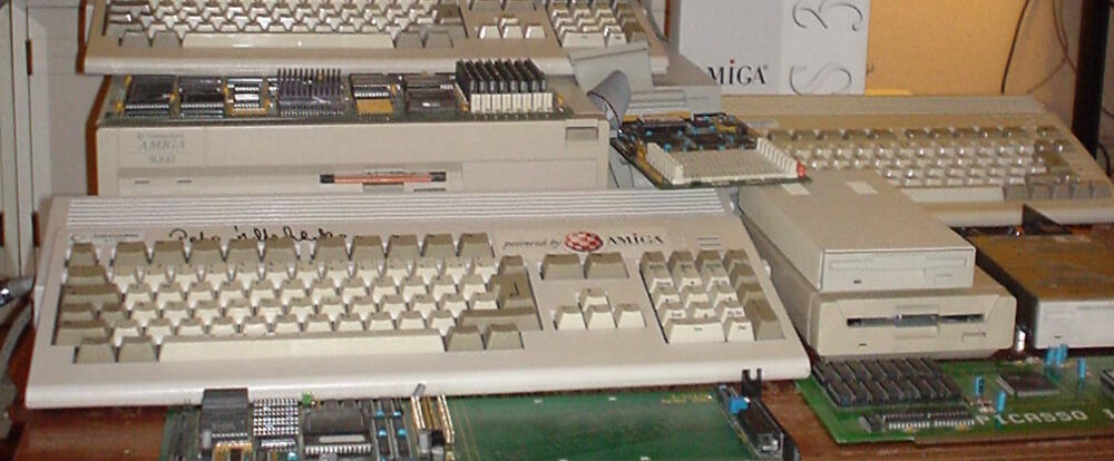
I used this riveting tool to rivet the sides back to the case once they had been cut off and modified. I bought it back in 1999 when I was modding my then A4000D into a PC mini tower case. See that case below.

Those were the days…

And here I am almost 30 years later using it again (for the second time) for the same purpose.

Make no mistake, the rivets and riveting tool works great for securing case sides and makes for a very stable case again.

Test fitting Amiga 4000T motherboard, daughter boards and Zorro cards in the modified case

More test runs with the case, this time trying out a 5.25″ unit in the top bay

I was now at a point were I could test fit cards and other hardware in the case to get a feel for what would fit and what would not fit.

Trying out A4000T daughter boards in the case. They fit fine.

One thing that hit me is how roomy the case is, inserting full size Zorro cards is a no-brainer in this case and is a real pleasure to do. The daughter boards unique for the Amiga 4000T also fits great in the case.

The daughter boards for the A4000T line up beautifully on the back of the case.

The daughter boards can be accessed fine from the backside.

Testing out a few Zorro cards in the A4000T.

Full size Zorro cards fit without problems in the old AT case. Even my A2386SX slides in and out without problems here. That is great for being such a small case relative to the original A4000T case.

Oops, we have a problem with the gap for the Zorro card brackets.

But one problem was quickly noticeable, the Zorro boards are offset slightly. I fixed it by adding spacers under the brackets.

Finding and installing a PSU that would fit in the case for the Amiga 4000T

Chosing a Flex-ATX PSU for the A4000T

There was no space for a regular ATX, AT or SFX PSU. After an intense brainstorm session were I played with the idea of using a Pico-PSU and an laptop charger I Instead opted for a NOS thin Flex-ATX PSU.

Flex ATX PSUs are smaller than a regular PSU and are quite popular these days because of tiny PCs. This PSU has 12a on the 5V line and has a total wattage of 250W. I have always steered away from PSUs with 40 mm fans because they usually create a ton of noise. This PSU is not an exception, but the noise level is not that bad to what I have heard before.

ATX-PSU to Flex-ATX PSU converter plate

So how do you fit an Flex-ATX PSU to an AT/ATX case? I found this ATX-PSU to Flex-ATX PSU converter on ebay. It is a thick plate of aluminium and makes it possible to use the Flex-ATX PSU in a normal case.

Flex-ATX PSU installed and working in Amiga 4000T PC AT case conversion

The adapter plate fit great and holds the Flex-PSU securely in the case.

The Flex-ATX PSU saves a lot of space inside the case

This picture shows that there are plenty of space for the A4000T P8/P9 power connectors and the turbo card. As the Flex-ATX PSU is short the case can still take a full length 5.25″ drive in the upper bay.

The PSU cables takes up a lot of room in the case and are not needed

One problem with the Flex-ATX PSU was the cables. They were long and took up a lot of space in the case. Just look at the image above. What is not shown is the AT to ATX adapter taking up even more space.

Cables for the Flex-ATX PSU are seen pruned

So I cut off cables I would not need. I also wired the AT to ATX adapter directly to the PSU and shortened cables. This made a huge improvement to cable management in the case.

The AT to ATX converter was wired directly to the Flex-ATX case.

A picture from the top shows cables neatly tucked under the PSU. I saved some SATA power cables because you never know, could be usefull in the future.

Wiring up the I/O board to the A4000T motherboard

Test fitting I/O board, that is missing 25p DB connectors

The I/O board gave me a couple of problems. The first problem was to find suitable D-SUB connectors. The D-SUB connectors on the Amiga 4000T I/O board has to be a little bit taller than regular straight D-SUB connectors as otherwise the I/O PCB board will hit the case.

DB25 pin F/M straight connectors with hex nuts glued on to them

The D-SUB connectors I got was quite expensive but options were few. The only ones I found was D-SUB connectors without threads for the hex nut so I had to glue nuts to the D-SUB connectors with Epoxy glue. It was a nasty solution but works.

Extended straight DB25 connectors

I used a strong epoxy glue and let it cure for a few days. The picture above clearly shows the extended D-SUBs needed.

40p headers are desoldered and waiting to be soldered to the back of the I/O board

During a test fit of the I/O board I found out that there was no space for the pin header. The I/O board is hooked up to the A4000T through two 40 pin cables called short and long. The pin header is usually facing down from the board on the front side but that would not work as the they would hit the case.

So what I did was that I desoldered the angled pin headers and soldered straight pin headers to the back of the I/O board instead.

Amiga 4000 I/O board with pin headers soldered on the back of the board

Then I ordered four 20 pin single row cables from AliExpress and hooked everything up. As it was not entirely clear how to exactly mount the cables I accidently hooked them up wrong.

But after thinking really hard for 30 minutes (including drawing up a routing scheme) I figured out the right way the cables should be mounted and everything worked as is should. Please keep in mind that the cable is installed in the wrong direction on the picture above and below! This part of the project was extremely confusing for some reason.

A4000T I/O board finally mounted with short cables

I am very happy with how it turned out. However I would prefer 40 pin cables as they are easier to insert and remove. Maybe I will wire up custom 40 pin cables in the future because these 20 pin cables need a lot of force to be inserted correct into the pinheaders.

Modifying the 3.5″ drive bay to fit the case with the A4000T motherboard installed

3.5″ floppy drive for the Amiga 4000T mounted in its drive cage

I do not use floppy drives anymore but I had this 1.76 MB floppy drive in my stash that I got in a trade for free and thought why not. Could come in handy in the future. To fit the drive bay it had to be cut on one of the sides to make way for the motherboard and I had to figure out a way of securing it to the case as it was riveted to the case.

The drive cage has a PC speaker that the A4000T has a pin header for

Interestingly it has a small speaker on the underside. The small speaker actually comes in handy since the Amiga 4000T has a pin header on the motherboard for a speaker that can play Paula output (controlled by the turbo button).

How the 3.5″ drive bay was mounted to the case once it was modded

To secure the 3.5″ drive bay I screwed it down on one side with a nut and screw. As the 3.5″ floppy drive sits a bit tight in the front of the case it does not really matter that only one half is screwed to the case. It is not perfect, it is a bit flexy when ejecting floppy disks but works fine.

How the floppy drive looks like on the front of the A4000T case

And here is the Amiga floppy drive installed in the A4000T case. Now, what to do with the upper 5.25″ bay?

Installing something in the 5.25″ bay

I installed a CD-ROM drive in the upper 5.25″ bay just for completion purposes. It is not like I actively use CD-ROMs anymore. I would prefer a ZuluSCSI or Compact Flash bay here instead and will probably exchange it in the future for that.

Installing power button

Installing a power switch for the A400oT

With all DIY projects there are problems that needs to be solved, even with a silly power button. The screw holes for the power button did not fit the case so I super glued hex brass nuts to the front and screwed down the power switch to them.

I did try to find a better fitting power switch but found nothing that would fit better.

Figuring out a better way of mounting the Amiga 4000T motherboard to the case

Experimenting with hex standoff nuts and plastic plugs to securing the A4000T motherboard

Some mounting holes on the motherboard lined up with hex standoff nuts already installed for installing the motherboard in the case. There was also space for these plastic plugs. I was disappointed that the motherboard was not really that securely attached to case with the mounting solution of a few brass hex standoffs and plastic plugs so I looked for an alternative.

Going the hex standoff nut and spacer route to secure the motherboard to the case

What I came up with was to use two washers and a brass standoff with a slightly longer thread.

Brass hex standoff and spacer

Here is a hex standoff with a washer.

This is how I secured brass hex standoffs to the case where the hole was too big

And here is how the brass hex standoffs are secured to the case by screwing it down with a nut having the case back wedged between two washers. I put Loctite on the threads to make them stick and I also glued washers to the case before screwing them down tightly.

All brass hex standoffs secured to the case, time to install the A4000T motherboard

This is a great picture that shows all mount points for the motherboard. What I especially like is the full support around the ISA and Zorro area. Inserting or removing a Zorro card leads to minimal flex in the motherboard or the case. Inserting and removing Zorro cards is pure pleasure in this case, even bridgeboards thats slots into both the Zorro and ISA slot. Please note that there are hex standoffs on the upper area too, the A4000T motherboard is huge!

Amiga 4000T motherboard fully secured to case

The Amiga 4000T motherboard is fully secured in the AT case. I thought everything was fine but I had just created a big problem, can you guess what?

Fixing offset problems for daughter cards and Zorro cards

The problem was that adding a 1 mm washer under the hex standoff pushes the motherboard further out. That meant that cards did not sit flush against the back of the case.

Off course I could have fixed this with shorter brass hex standoffs. But as they were already screwed down tight and glued and loctited I just decided to find another solution. And that was to add some thin washers under the bracket for the daughter boards.

Kinda weird but the Zorro boards sits further out than the daughter boards. So I needed thicker spacers here. I do not know what it is but no matter what Amiga project build I work on I always have problems with offset cards in all my builds – so I was not surprised here.

I used epoxy glue to fix them to the back. It is possible to 3D print something to fit here or to order some custom machined plate. Maybe in the future. It might look naff but the spacers actually work, cards sit very solid in the case.

Final thoughts

The A4000T is populated with some Zorro cards and a BFG9060.

While the build is not finished yet, the case sure is. In its current state it has a Multifix scandoubler, and a Matze graphics card. A 256MB memory card and a Zorro-LAN-IDE card. There is also an AmiGUS in it and a cool red BFG9060. There are small things to do here and there like cleaning up the cables, adding power to the CF adapter and installing a ZuluSCSI, a bridgeboard with ISA cards will also go into this case. Building a bad-ass PPC workstation is also a potential future for this build as it has the potential for much better case cooling than the A4000D has.

And I must not forget, I need a boing ball badge for the front.

Some Amiga activites I have worked on in December

I have worked on some small things here or there on my Amiga computers. Here are some noteworthy things that has kept me busy.

Installation of an 2.5″ angled CF adapter in my backup A1200

These angle 2.5″ CF adapters were popular 20 years ago

I found angled 2.5″ CF adapters on AliExpress. I have been looking for these for quite some time. They can not work if you have an Indivision AGA in your A1200 but if you do not have one they offer a great reliable way of running an internal compact flash drive in your Amiga 1200. There was only one problem:

This one has a pin blocked, probably to keep you from frying it by mounting it 180 degrees wrong

They came with one pin blocked. I used a small drill to drill into the blocked pin and realised that it was only the top layer that was blocked. Next step: try it out in my backup A1200.

How nice, a genuine C= Amiga 1200 case and keycaps

My backup A1200 has 3.1 Kickstart roms so I had to upgrade the Kickstarts before trying an Workbench 3.2 installation. So the next step was to flash some roms with AmigaOS 3.2.

FlashROMs are programmed with DiagROM and Kickstart 3.2

Here are the FlashROMs. I decided to flash DiagROM and Kickstart to them as they can hold two ROM images. It is very handy to have DiagROM availble if needed.

A white ReAmiga 1200 matches the case nicely

My backup Amiga 1200 looks like a regular A1200 on the outside but inside it is a white ReAmiga 1200 that I built a couple of years ago.

The more LEDs the better

Here the FlashROMs installed. But it failed to boot into the Kickstart screen, DiagROM worked though. So out came the T48 programmer and FlashROM adapter again. It was impossible to flash the FlashROM again. After 30 minutes of fail checking I realized that I used the wrong USB-A cable for the T48. After swapping cables the correct ROM image was flashed and everything worked.

The ReAmiga 1200 has a kickstart switch built in it

The ReAmiga 1200 has a nice Kickstart switch feature that you can enable. If enabled you can chose between two different ROM images through a jumper. If you do this with a FlashROM you do not need to jumper the FlashROM. As you can see, I never bothered to solder on the fan headers.

The angled 2.5″ CF adapter fits the A1200 motherboard fine

Here is the CF adapter mounted on the internal 2.5″ port of the ReAmiga 1200. Booting off of a WB 3.2 installation it worked fine.

I am using an old school external 23 pin scandoubler, thats why the image is a bit dull

Making the ReA4091 work with a BFG9060 clocked at 100 MHz
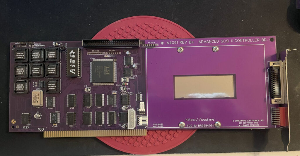
ReA4091 SCSI2 Zorro 3 card

I had problem with my ReA4091 SCSI card when running my BFG9060 68060 turbo card at 100 MHz. The Amiga 4000TX worked fine if the BFG was clocked at 50 MHz but at 100 MHz the system refused to run stable giving me filesystems error instantly in Workbench.

This is not a new problem as many other has had it. But at the same time, many have gotten A4091 and a BFG with a 060 clocked at 100MHz working without trouble.

I got a heads up about a thread on github discussing possible solutions to this problem. You can find it here. One suggestion there is to reprogram U305 with the file from here.

Apparently this fixed the problem for the user who suggested it on github with a drawback of 10% less SCSI performance.
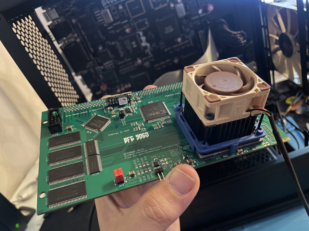
BFG9060 with 68060 rev. 6 clocked at 100 MHz

I did not have anything to lose so I decided to give it a go by flashing the little PLCC chip with the file suggested. To my surprise it actually made my hardware setup stable again at 100 MHz! Now that I have put in a few hours in my system I can confirm that it runs stable (and now more than 6 months later I can confirm that it has been working great).

This particular build consists of an A4000TX, BFG9060 with a rev.6 68060, ReA4091 with a ZuluSCSI compact, there is also a ZZ9000 graphics board in the setup. It is my main setup.

Solas + ISA board installation in my A4000TX

I have a Solas LED controller in my A4000TX, it is hooked up to an ISA carrier and is connected to the clock port on the Zorro-LAN-IDE card. It took a while to figure out how to connect them together and to get sound into the Solas. But after tinkering with it for a few hours it is working fine now.

The sandwich card of the Solas carrier and Solas is too thick though, making it difficult to run a full size Zorro card over it, I am thinking of soldering them together to decrease the height of the card sandwich. It could either be the greatest thing ever or the greatest disaster ever, I will need to flip a coin on how to proceed with this idea.

Second A2386SX board built and tested

I like to build things I like in pairs that is why I did not hesitate when I was given the opportunity to build a second A2386SX clone again. You can see some more pics in the previous link. I do not think I will build more of these boards as they have given me a tough time both in getting them working and in sourcing components for them.

A4000T AT case mod

Mid size PC AT case from 1998

I did not hesitate to jump on the train when an A4000T replica PCB was offered for sale on Amibay a few years ago. Building it was a lot of fun and also fascinating. The A4000T is after all the final official 68k Amiga computer released.

I was too naive expecting a case to show up by itself. Now I realize it might never show up so I decided to look for solutions. There are ATX options but I wanted to try an old AT case first.

The universe was aligned with my third eye and suddenly an AT case manifested itself on a local trading place. But the struggle is real, nothing comes without pain and struggle. The A4000T motherboard is huge, it wont fit this case without some cut fingers on old sharp PC case sheet metal edges and serious case modding. And I hate hardcore sheet metal case modding and cutting my fingers on old shitty PC cases.

The A4000T motherboard actually fits inside this case, but it will take some serious case modding to make it happen!

But once modded though, the 5.25 bays the case has wont be usable any more. It wont be able to take an AT or ATX PSU anymore either. But hey, when it is fully modded, at least I got a case for the A4000T where the daughter boards line up perfectly on the back of the case. I just need to figure out how to mod this case in the simplest way possible.
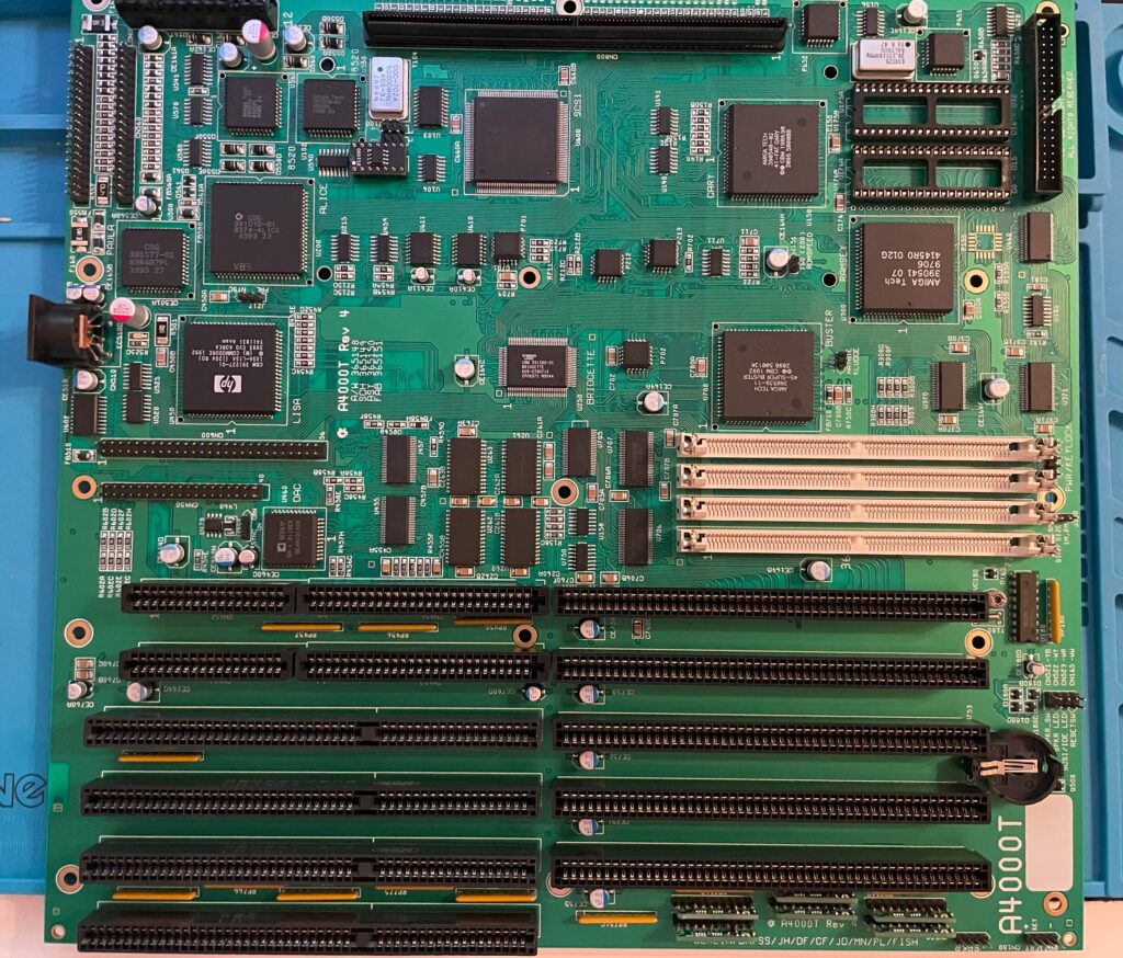
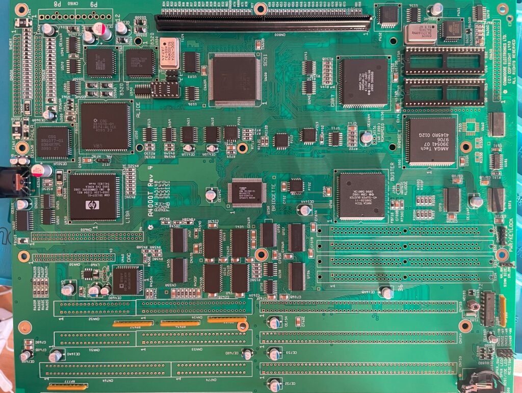
Finishing the A4000T build and looking back at the build process

I finally got the last part that was missing from the BOM from a seller in Germany so that I could finish my Amiga 4000T motherboard replica build.

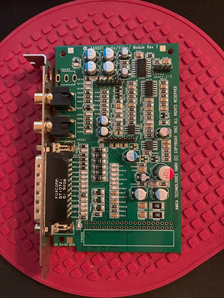
The motherboard is fully built, so is the AV module, the disk module and the ATX I/O module.

Unfortunately I do not have any AT PSUs anymore. I have ordered an AT to ATX converter, hopefully I can test the board once it arrives next week.

Looking back at building the Amiga 4000T

I think this build was fairly easy. The most difficult thing was locating parts on the PCB, thankfully there is an Ibom for both the main board and the modules here. If there was no Ibom, I honestly dont know how I would placed some of the components as placement can differ from Commodore made PCBs. You can not just compare part placement on pictures.

I will go through the build in more detail when I have tested the board fully.

Almost finished with my Amiga 4000T replica build

I am happy to say that my A4000T build is soon finished. I am waiting for some pinstrips and a couple of passives I missed out on in my first order of components. When I get them I will proceed with the video and Zorro slots and also the three ISA slots (and the P8P9 power connector).

I am always nervous when soldering the 200 pin KEL CPU card connector. If you do it wrong side, you have to desolder it and turn it around – that is a lot of work. Better option is to triple check everything before soldering.

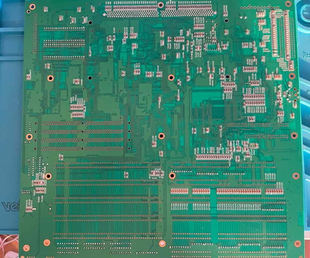
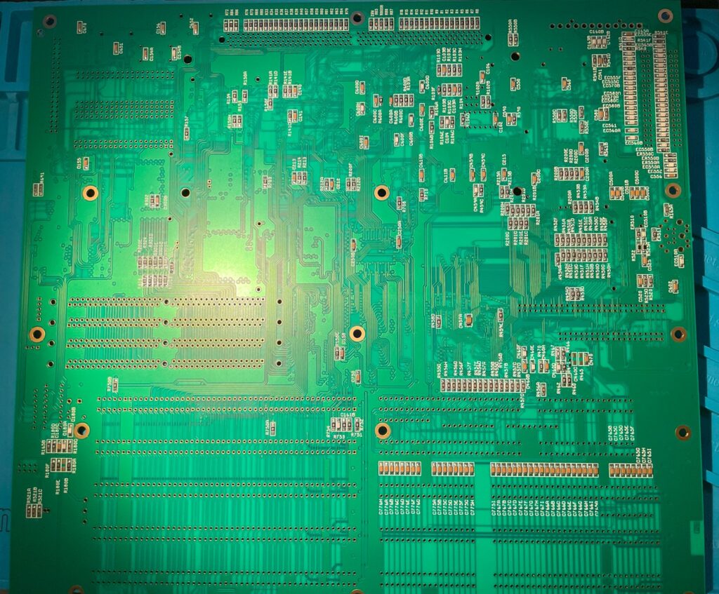
The backside of the A4000T PCB contains a lot of passives to solder on. All passives are 1206 though installation went fairly smoothly.

All thats left to do is to solder in the pin strips, 72-pin SIMM sockets, P8P9 socket, edge card slots and some small parts and then I will clean up the bord, inspect everything twice and do a test run with Diagrom. You can be sure I will post about it here!

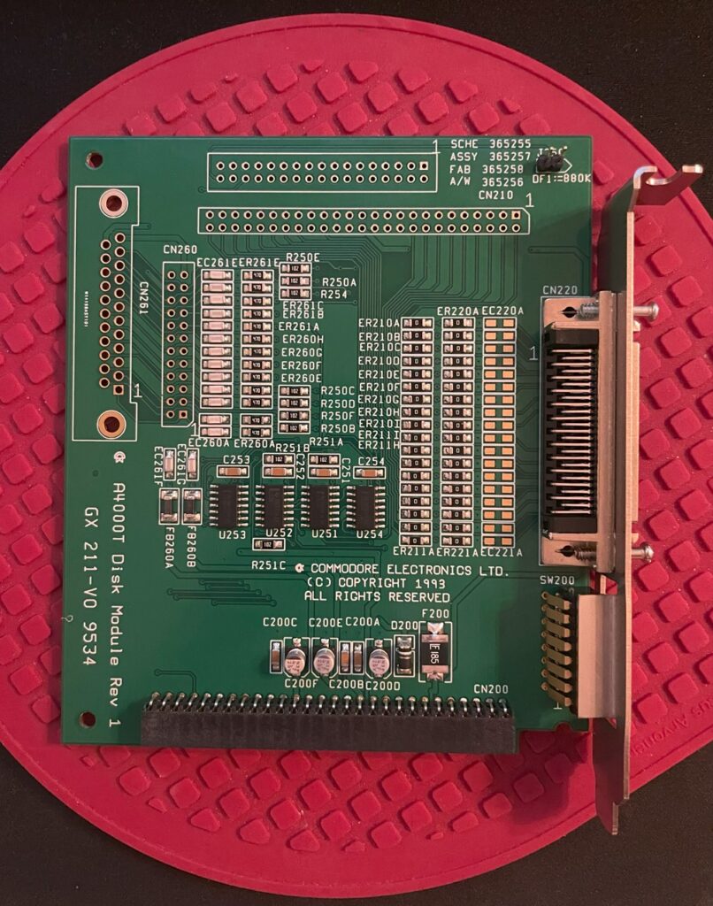
Amiga 4000T disk module (replica build)

I am building an Amiga 4000T motherboard and its modules at the moment. Here is the disk module for the A4000T. It is almost fully built, missing two double row pin headers and screws for the external SCSI2 port.

The disk module has the internal 50 pin SCSI port and the external SCSI2 port. It also has the SCSI switches (accessible from backside) and floppy port. It is attached to the Amiga 4000T motherboard on a pin header.

Amiga 4000T AV module (replica)

Work continues on my Amiga 4000T replica build. On the A4000T a lot of functionality is placed on daughter cards such as audio and video out that is placed on the AV module. The A4000T AV module slots into the Amiga 4000T motherboard in a 40 pin 20 x 2 double row 2.54 mm pin header.

As you can see on the image above, the AV module is about 95% done. It is missing the headphone jack, 20 x 2 double row female connector and two 3904 transistors (and some jumpers).

Finished all the passive components on my Amiga 4000T replica build

Backside of the Amiga 4000T replica motherboard

I am currently building an Amiga 4000T replica that I got from Amibay. I got the components from Mouser last week and spent the weekend starting the build. There was a lot of components to solder on this and I am far from finished, but happy to say that I am finished with 90% of all passives. Backside of the motherboard is finished!

I still have a ton of 1206 passives to solder on the daughter cards. But those will be far smother to build since the cards are smaller.