I finally got my hands on the PowerShark Power Adapter for the Amiga 500/600/1200. There are many PSU options for wedge Amigas these days but the PowerShark power adapter in combination with a USB-C PSU for the Amiga was a nobrainer for me to choose because of two reasons: It is USB-C and it has a power switch close to the Amiga 1200.
USB-C Amiga PSU
I highly suspect USB-C will become even more widespread in the future for retro gear, not just for Amiga computers. I suspect most vintage hardware will be able to be modded or will be able to made run on USB-C with some hardware device – meaning, one main PSU could drive many devices instead of having multiple aging PSUs.
The power switch situation
Having a power switch close to the Amiga is a luxury. No need to reach for the switch on the floor anymore.
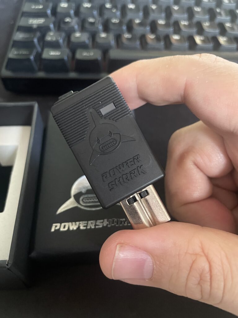
Lets take a closer look at the PowerShark Power Adapter for Amiga
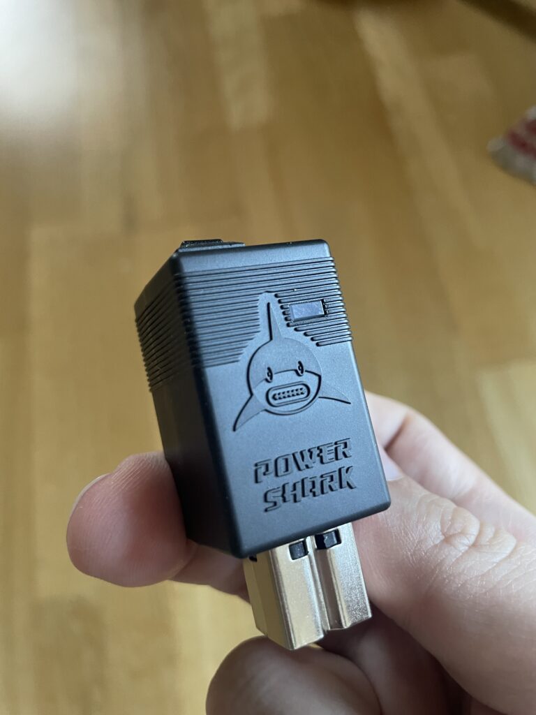
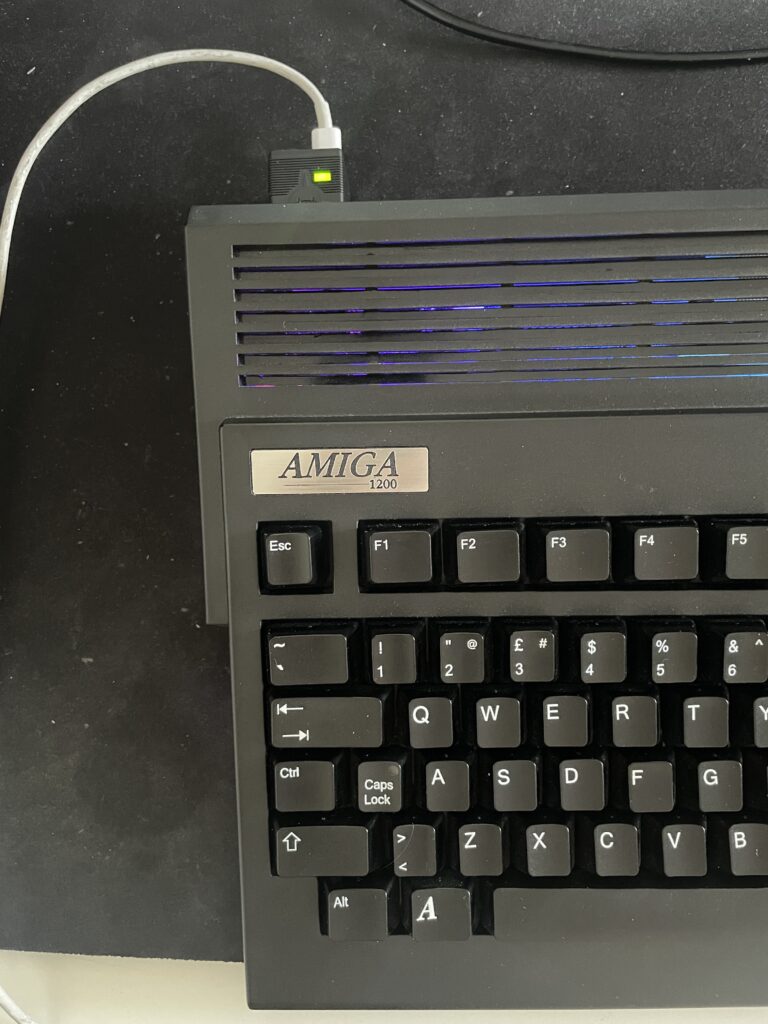
The PowerShark power adapter is a neat little piece of hardware that inserts into the power socket on the Amiga 500, 600 or 1200. It has a LED that lights up in either red or green, red if the PSU driving it fails or green if everything works. The plastic shell is quite nice and looks professional.
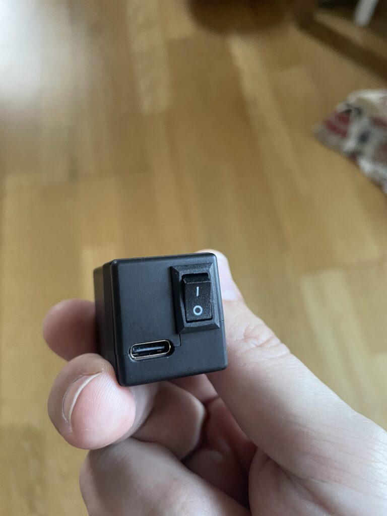
The backside of the PowerShark power adapter for the Amiga has a small on/off switch and the USB-C socket for powering it from the USB-C PSU.
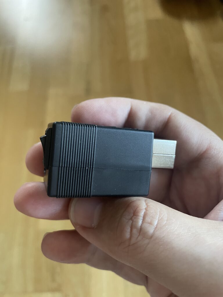
The side view shows its small size. The size of the PowerShark is 25 x 27 x 58mm.
How to power the PowerShark Power Adapter for the Amiga?
The PowerShark has to be fed power from a USB-C PSU. As you may know Amiga runs on different voltages so PowerShark Power Adapter has to be fed 12v. The 12v then gets converted into the different voltages the Amiga needs to run in the PowerShark. That means the USB-C PSU has to provide 12v or else it wont work.
Besides providing 12v the PSU has to provide enough amps or else there wont be enough power to power up the A1200 (a 5w phone USB-C charger wont run an A1200).
I tried with my laptop charger and it did not work because it did not provide 12v. But another USB-C laptop charger I had worked fine since it could provide 12v. If in doubt, it is usually specified on the charger if the USB-C PSU outputs 12v.
I also tried with a low end Apple charger (5-7w IIRC) and that did not work either as expected, the PowerShark just got a red LED.
For testing purposes I fell back on this 20w USB-C phone charger i found at home pictured above. I will for sure upgrade to a more beefy USB-C PSU later but for now this will do fine.
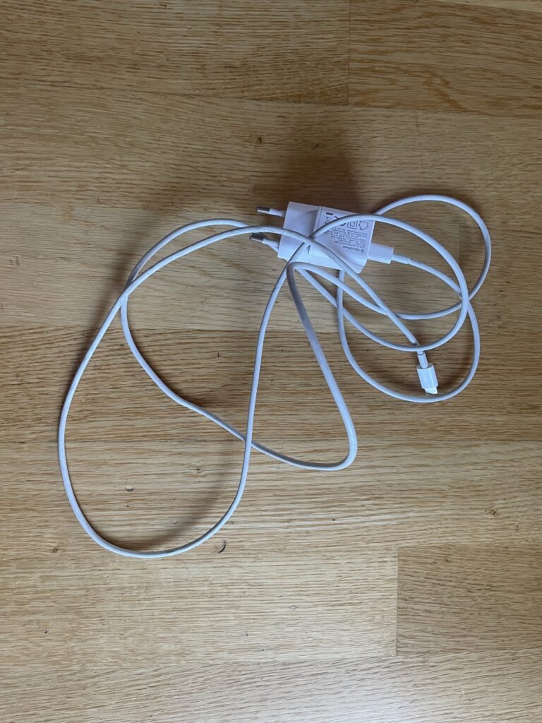
There are some details on the homepage about the USB-C cable that you should use. I just took the safe route here and used an old Apple USB-C cable that powered an old Apple laptop i had years ago.
A nice cheap alternative is to get the RaspberryPi 5 27w USB-C PSU. But that one seems not to be available in black.
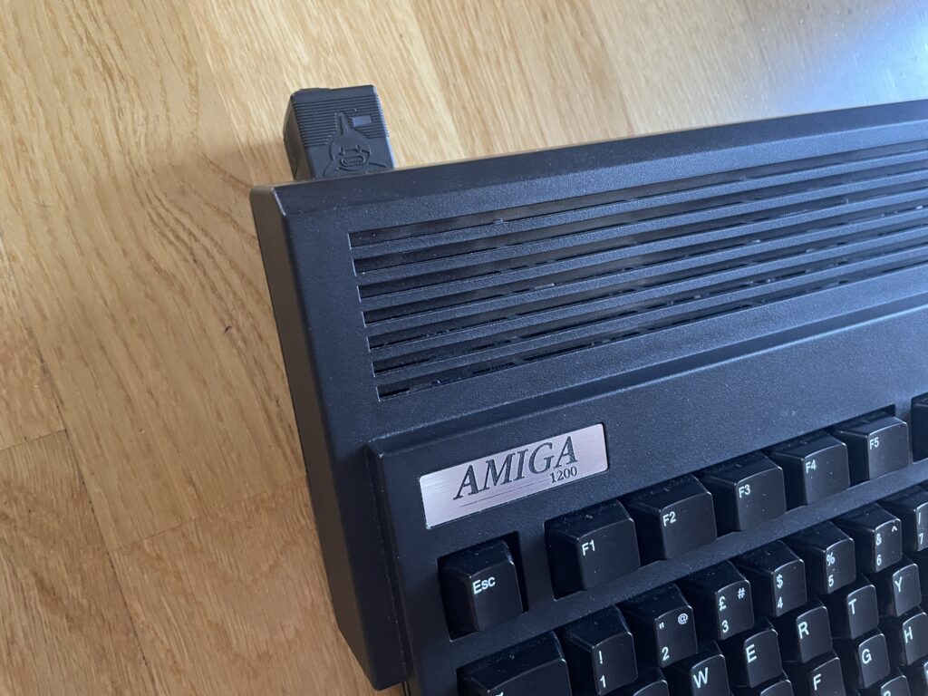
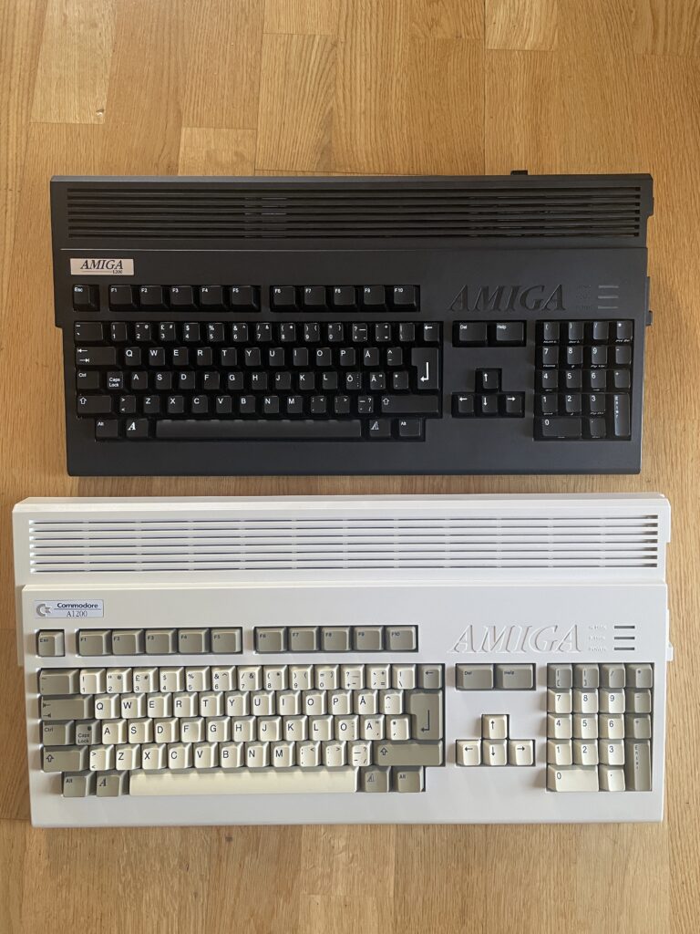
As my main Amiga 1200 is black I wanted a black PowerShark and I think it goes well together with it. It sticks out a bit at the back but it is not that bad I think.
The Amiga 1200 I used for testing consists of the following hardware and is my main A1200 (and the Amiga that gets the most use by me except the A4000TX):
- ReAmiga1200 1.5
- TerribleFire 1260 128MB/060@100Mhz
- Indivision MK3
- Solas + one LED strip
- MicroniK floppy drive
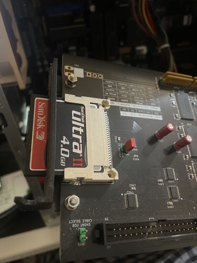
- 4GB Compact Flash
- PicoWyfy
- MouSTer + USB adapter for mouse
How much power does an Amiga 1200 use

I wanted to test the stability of the PowerShark and came up with a mini test. I got an idea to run a few programs that pushes the Amiga 1200 hard. I ran both Quake and Quake 2 for a few minutes and also ran a fractal generator on my A1200 with 68060. Everything worked fine – keep in mind this was not a 24h test, but more a half hour test.
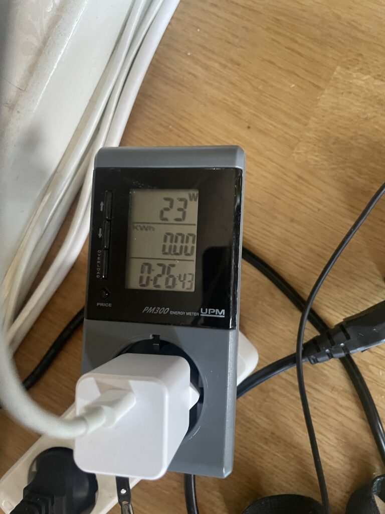
I got this power meter years ago and it is quite fun measuring devices. While pushing the A1200 above hard the watt meter tops out at 23w. During idle it sits between 18-20w and during regular use around 21w.
My USB-C PSU is rated at 20w so I wont run this setup permanently as that cant be too good pushing it too hard but its interesting that stability was not an issue.
But that got me into thinking, how much power would a regular Amiga 1200 draw. I have a backup A1200 that is completely stock (except its also a ReAmiga 1.5).
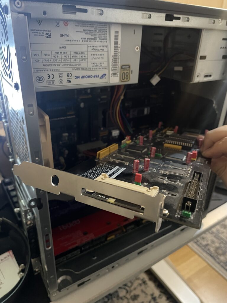
This A1200 has: A CF adapter without CF card and a 3.5″ floppy drive, other than that, its completely basic.
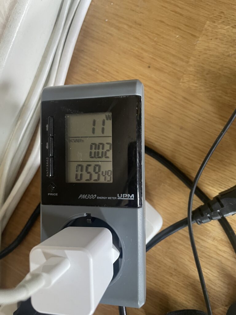
And here it is powered by the PowerShark Power Adapter and is hovering between 9 to 11 watts.
Final thoughts
I have no regrets, this is a great addition to my Amiga 1200.
You could say it is an expensive solution since the PowerShark costs 80 euros and you need to get a USB-C PSU (and USB-C cable if PSU does not have one) so that adds to the price.
You could also say it is a complex device because you need to have a specific 12v USB-C PSU that can provide sufficient amps. There are many great options for USB-C PSUs mentioned on the website and for the average Amiga user I highly suspect this is not a real problem.
It is what it is but I think that you pay a little bit premium to have a modern solution and that is something I happily will do. I would happily pick up another one if I was knee deep in wedge Amigas only!