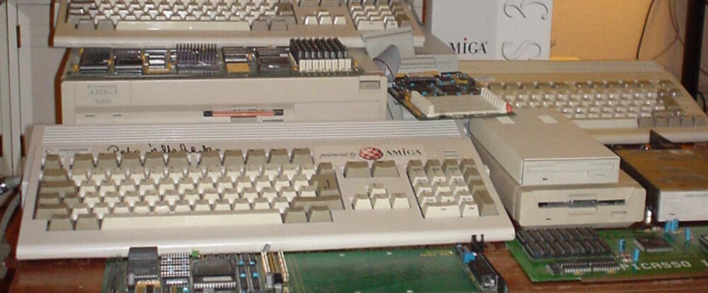
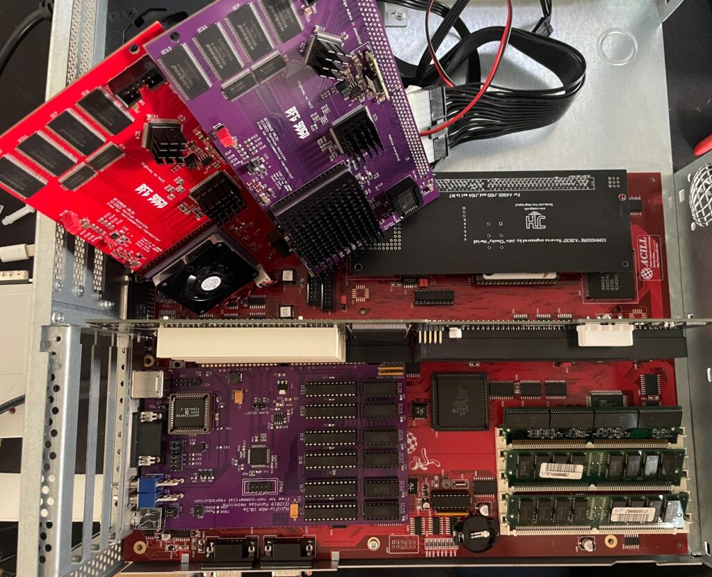
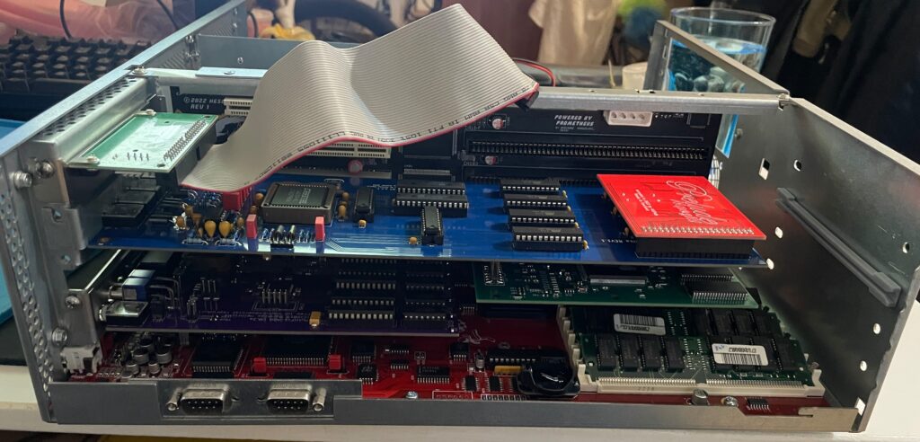
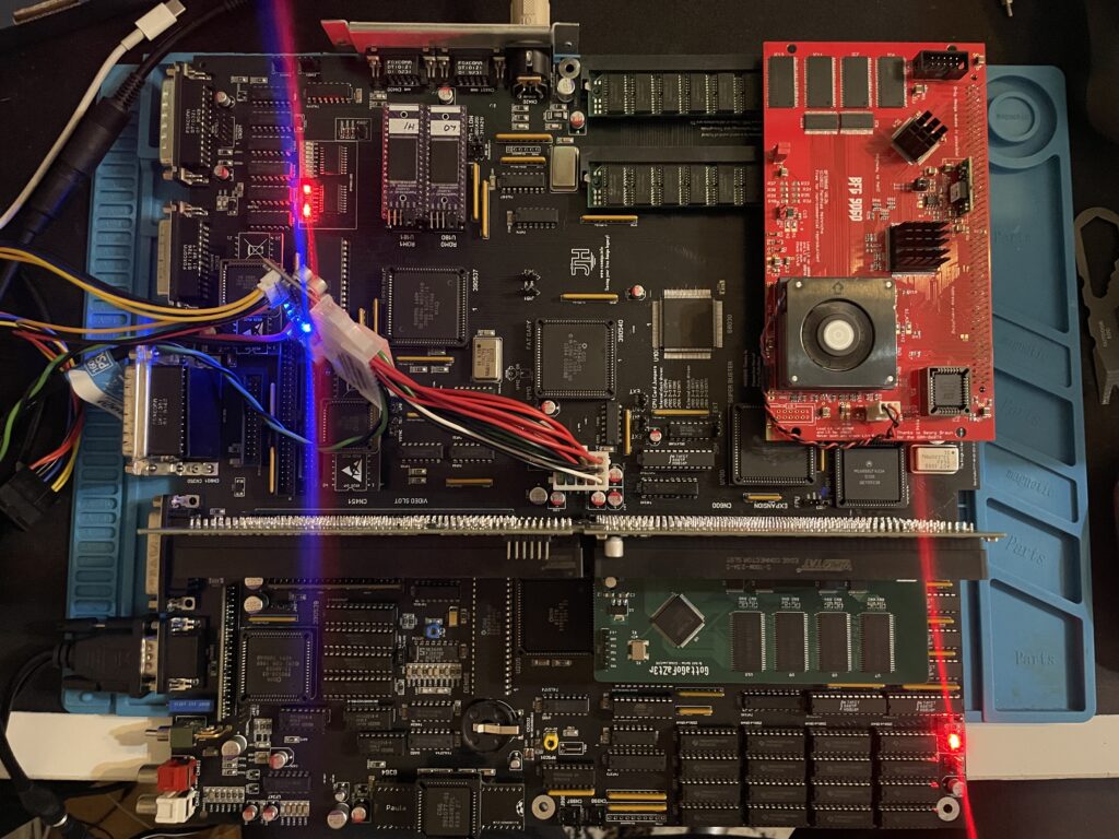
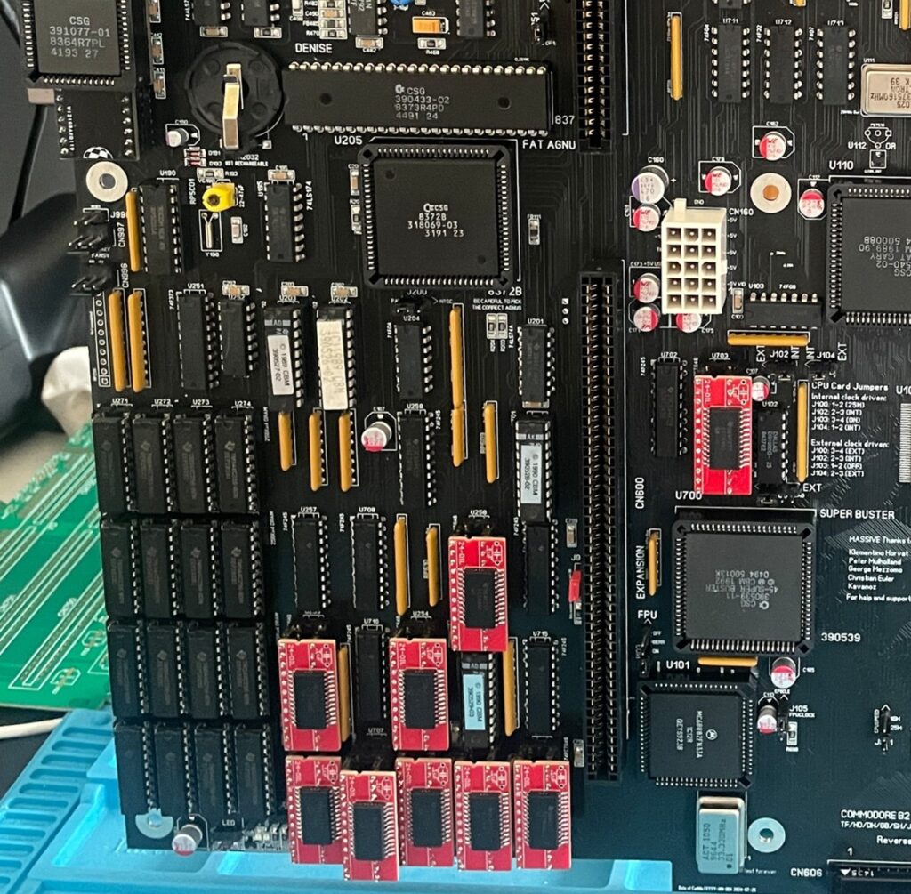
Here is my test setup: Acill A4000D motherboard with ReA3630 and two BFG9060 cards including Firestorm PCI daughterboard, Multifix-AGA and a replica A4000D case
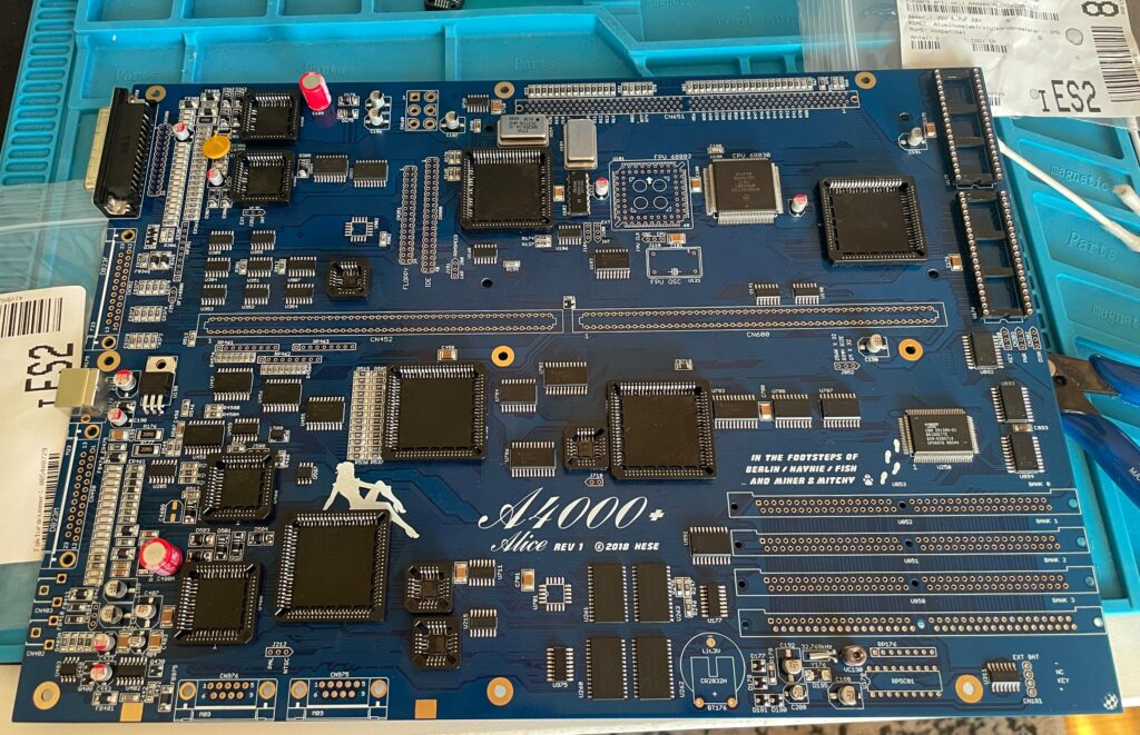
I had two summer projects this year that I recently finished. One was an Acill A4000D replica motherboard and the other was a Hese made A4000+ Alice A4000D CR motherboard replica. You could say two brothas from different mothas or something…
Both motherboards worked fine when doing basic test runs, however they both failed to run with a BFG9060. All I got when running them with a BFG9060 060 CPU card was a black screen.
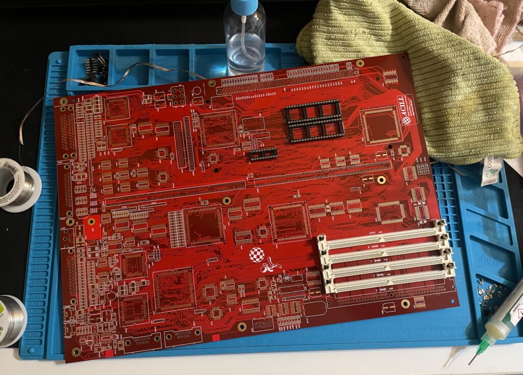
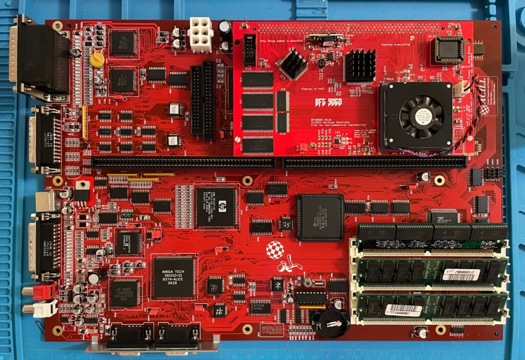
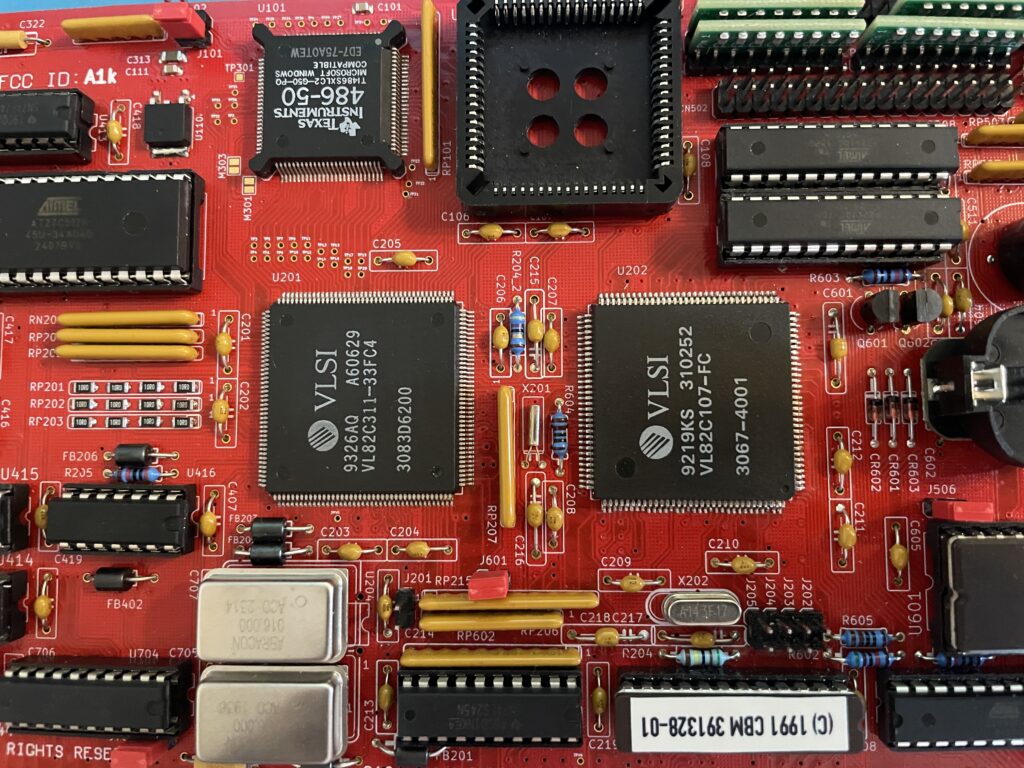
Amiga 4000D motherboard in shiny red
Anyway, as usual building them up was pure pleasure from start to finish. I even enjoyed desoldering the Acill A4000D motherboard from a few passives and pin headers someone else had a false start with. I mean, off course you want a full set of pin headers soldered to your 400+ small parts PCB (not really).
As good as it was looking it failed to run with the BFG9060. It was working fine with the A3630 CPU board I built earlier this year, but not with the 060 card. That reminded me that I had the same problem with my Alice A4000D motherboard a couple of weeks ago.
A4000+ Alice motherboard during assembly phase
The Alice A4000D has an 030 CPU on the motherboard so it does not need a CPU card. It was working fine with the on board 030.
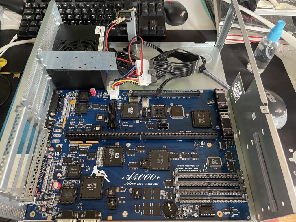
Here is the A4000+ Alice motherboard during the testing phase inside the A4000D case
I got the suggestion to try a new delay line as that could be the problem the CPU card failed to run. As the A3630 has exactly the same CPU as the one mounted on the motherboard, it is difficult to say if the A3630 was running or not.
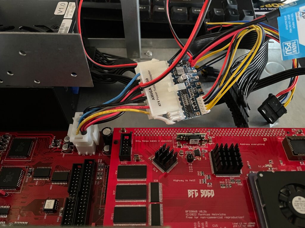
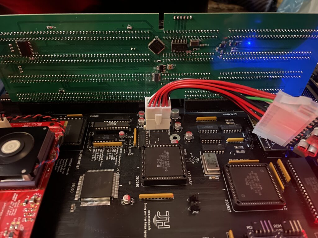
Testing the A4000D motherboard + BFG9060 with a PicoPSU
If you are in this hobby you have to grow a passion for trying all hardware combinations to find the solution. In this case, the reason for the Amiga 4000 getting a black screen when running a BFG9060 was the PSU as everything seemed to run fine with another PSU than the SFX one I had in the A4000D case.
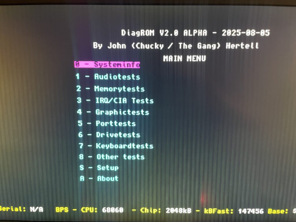
I changed the SFX PSU that previously was working fine with the EXACT hardware setup I am running here (but different Amiga 4000 motherboard) with a small ITX PSU and suddenly DiagROM worked fine and detected the 060 CPU.
This lead me to believe that maybe the PSU was not pushed too hard as some ATX PSUs fail to run if there is a tiny load on them (or something like that). So I decided to do a final test by adding some cards to my A4000D and try the SFX PSU again.
Unfortunately it did not start with the SFX PSU and 060 card even if I loaded the machine with all Zorro slots filled, including adding an old 3.5″ harddrive.
So next step is to get a new SFX PSU. But at least I know I have to working motherboards!
Update! 20251215
Apparantly it was the Kickstart that was the problem.
You may have seen my previous post where I did a test run on my ReAmiga 3000 that I finished earlier this year. If not, check out my post about my ReA3000 that I built in April here.
While I did do a test run in DiagROM previously I did not have a daugherboard for it so I just whent through the usual tests (successfully) and called it a day. This time I did a more comprehensive test session where I tested a Amiga 3000 daughterboard, a BFG9060, a GottaGoFaZt3r 256MB Z3 memory card, programmed and replaced the logic chips and also replaced some ICs that I had to use adapters for previously.
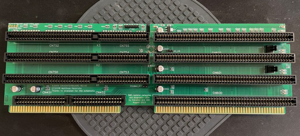
Amiga 3000 daughterboard
Front of the Matze Amiga 3000 DB
While my ReAmiga 3000 started up fine in DiagROM it failed to run with a Kickstart rom. I was puzzled about this since it was running fine in DiagROM. No matter what I tried I ended up with a black screen. Problem was solved by adding the daughtercard. Now Kickstart boot screen came up.
Backside of the Matze A3000DB, here is where the I2C circuit resides
I am using a Matze A3000DB, more info on it here. This is just like a regular Amiga 3000 daughterboard but it also has I2C functionality so you can monitor temps. More info about I2C here, the added functionality is based on that project. So to be honest, I have not really fully understood I2C, perhaps I will do a deep dive in the future. I have an CPLDICY card I built last year and its neat to see temps. I am thinking this could be interesting to monitor if running a tight A3000 case with bad cooling.
Another note, this is a version of the Matze A3000DB with some added functions by kavanoz & CDH, see more here about this specific version of the daughterboard.
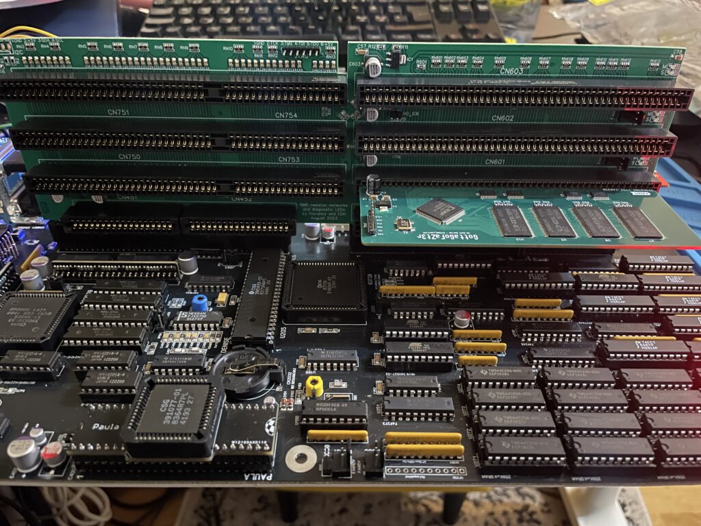
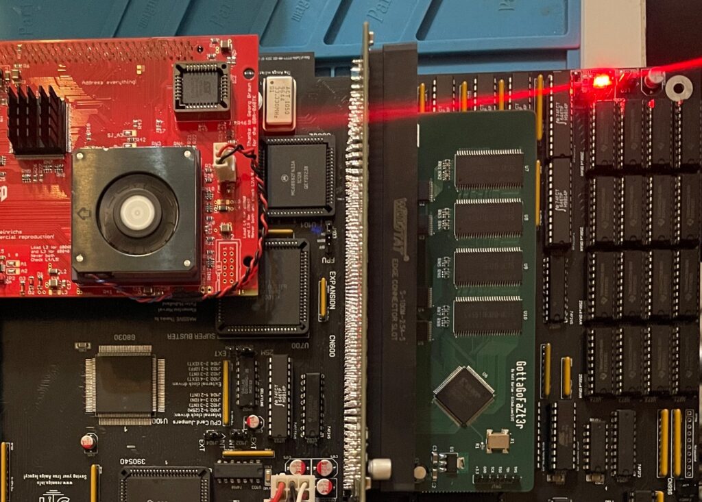
A GottaGoFaZt3r 256MB Z3 memory card was inserted and it was detected by DiagROM.
ReAmiga3000 + BFG9060 test, success?
The low profile heatsink/fan on the BFG9060 blows in the wrong direction, another thing to fix in the future…
Recently I built an A4000D that failed to run with a CPU card. That motivated me to test my older builds with a CPU card to make sure they work properly with a faster CPU. The only issue I had was to figure out how to jumper the motherboard, then it was smooth sailings.
68060 is detected in DiagROM (as is fast ram)
DiagROM identified the 060 and also the fast ram. Now I need to do a 6 hour fish render and stability will be tested (something to do for the future).
74FCT646 chip replacement
SOIC-24 to DIP adapters are the red mini PCBs. Also notice the original Commodore logic chips
If you look at the BOM for the ReAmiga 3000 you can see that Chucky recommends replacing the 74F646S with 74FCT646. Currently 74FCT646 can only be found in SOIC-24 from Mouser and Digikey and not in DIP so you need a SOIC-24 to DIP adapter to use them. While the adapter worked fine I just felt it would look better to run DIP chips instead. I had an UTsource order going for my A2386SX order in the pipeline so I added eleven 74FCT646 chips to that order from UTsource. Why 11 when the A3000 only needs 9? Well two of them is going to my A2386SX boards.
No more SOIC-24 adapters for a cleaner look!
The 74F646S chips actually runs hot, especially when there is 9 of them, that is something I noticed when using them from my donor machine. So it was a nobrainer to replace them with cooler running chips.
As I put in sockets for all the 74FCT646 chip adapters I am thinking of removing the sockets in the future and solder the chips directly to the motherboard for an even cleaner look. The ground plane in an A3000 is brutal though, not sure I wanna wrestle with this board desoldering stuff again. Desoldering the KEL 200 pin CPU slot was a nightmare.
Programmed and replaced logic chips
There are four logic chips on the Amiga 3000. About 15 years ago I had the oppportunity to buy a broken Amiga 3000 cheap because it had a broken display output. Turned out it was because one of the logic chips was broken, so it was an easy fix to just replace one of the chips with a new one.
So to future proof this ReAmiga 3000 build I replaced the logic chips I got from the donor A3000 with modern alternatives and got the JEDEC files to program them with from here.
Next step
I hope I can find a case for this build, they are difficult to come by but occasionally you can find one. Actually wish I had one now as I would like to set it up to a running system!
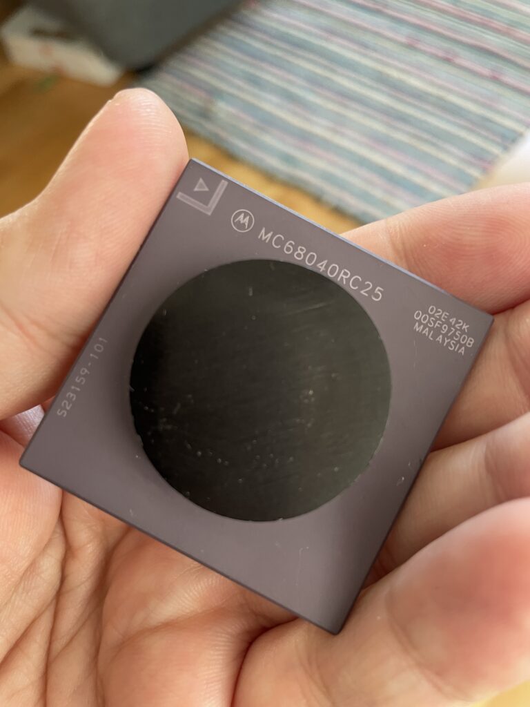
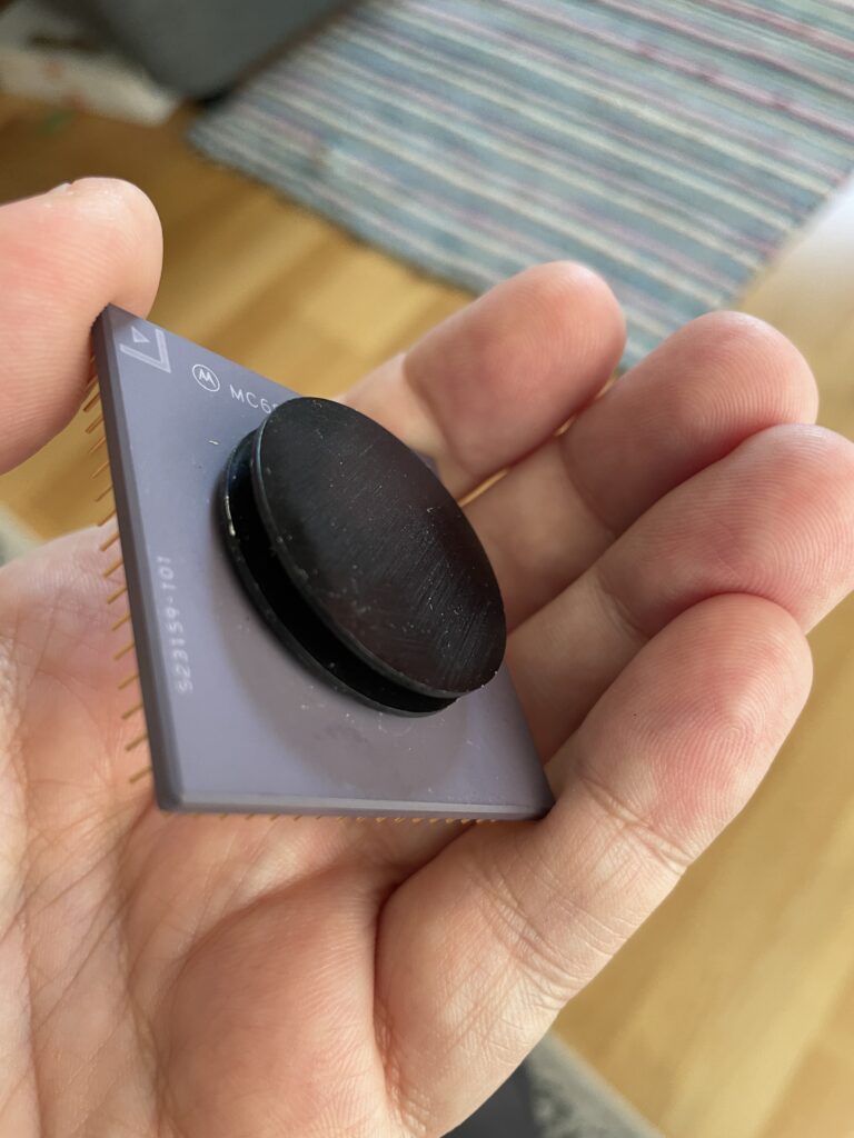
I got this Motorola 68040 25MHz CPU recently for a great price. It was too cheap not to buy. Interestingly, it is a later generation of the chip, manufactured in 1995 (or later). The 68040 is famous for being a hot chip. I remember that too well from running one in my Amiga 4000D I had back in 1998. But these later generations are made with a smaller manufacturer process, 0.65 micron vs 0.8 micron, so it should run cooler than the CPU on that crazy hot running Commodore 3640 CPU card I had.
I have not decided what to do with the 68040 CPU yet, for example, I have an old Apollo 1260 sans CPU that I could convert back to an 1240 and sell for 1999 euro on Amibay. While that is tempting, I think I would want to run this one in one of my big box Amigas instead as I am curious if it is overclockable and how hot it runs. I am also curious if the performance from the 040 CPU would be satisfying.
One irritating thing is that it has this silly flat and round aluminium heatsink glued on to it. Tried to remove it but it is bonded to it and wont move a micron. I was thinking of prying it off with a chisel and sledgehammer but got the idea to use fishing line or dental floss instead. No matter what option I take this pathetic heatsink will be removed one way or another and be replaced with a bad-ass P1 cooler with a Noctua fan. Maybe I have to spend a week grinding it off with my trusty Dremel from 1997 (hope not).
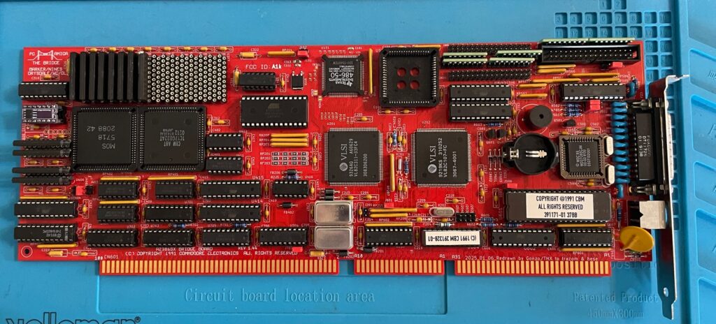
A beautiful replica of the A2386SX PC bridgeboard by Commodore.
This is an amazing replica of the Commodore A2386SX PC bridgeboard, you can find out more about the project here. There is also a discussion forum about the card on the German A1K forum (just use auto translate in your browser if you dont speak German).
Background
The A2386SX was the best PC bridgeboard Commodore made for the Amiga, it was based on a 386 CPU, could be expanded to 8 MB and enabled you to transform an Amiga in a multi CPU system that could run tasks in parallell on both CPUs, one in Amiga Workbench and the other in MS-DOS on the bridgeboard – at the same time. You could for example hop in to MS-DOS and run your programs and then multitask back to Workbench while programs where running in both environments.
This is a beautiful replica of the A2386SX PC bridgeboard by Commodore.
I got my PCB late in Q1 after contemplating if it was even possible for me to build this card at all. Building it was not the problem. The main problem was finding all the parts and programming some of the chips. But I quickly came to realization that it was actually possible to locate almost all the parts if I pulled the trigger at the right moment since some of the rare parts this build required was disappearing fast on Ebay.
My main goal of running the card is to have access to multi channel module players such as Cubic Player and to be able to play PC modules in MS-DOS with a Sound Blaster 16. I would also like to dive into some old MS-DOS applications I used to use 30 years ago and play some old DOS game or two. But the main attraction is PC music without having to get a separate PC just for that.
Some notes on parts and building the A2386SX project
The A2386SX was an old card so it uses ZIP ram instead of SIMM modules as does the replica
There are some very rare parts required for the A2386SX bridgeboard. The rarest chips are the two socketed PLCC84 Commodore chips and the PC chipset in the middle of the card.
The Commodore chips (MOS 5718 and the chip besides it) can be taken from 2088 and 2286 Bridgeboards (they are the same), they might pop up on eBay, but consider that a miracle if they show up. I got my chips from a cheap 2088 that I bought second hand last year. Did not know what to do with that card at the time, but it was too cheap to pass up on and I am glad that I got it now.
The PC chipset should in theory be easy to find online, but so far, I have only been able to locate one of the chips. The other chip needs to be ordered in bulk from a specialist in rare chips and is costly. I thought it was possible to find an old motherboard and desolder them from there, if you find a motherboard that has them – consider that a miracle!
Then we have other obscure chips such as the floppy controller, programmable chips (that needs a special vintage programmer or someone with better skills than me in understanding how to program them with a modern device) – not really a problem to find them.
ZIP Memory can be found from obscure part specialists (remember you need two types of memory). The CPU is available on eBay, but if you want the faster 486 that is compatible with the card, good luck, as said, miracles can happen!
A difficult to find item is the capacitor networks, you can cheat and use adaptors instead. I wonder if those are needed if you wont use a floppy drive with it though.
Bracket was sourced from another enthusiast who ordered a batch. 646 was taken from my donor A3000.
Full socket build
I did a full socket build, thinking it would make it easy to error check or replace chips. And if by miracle I would build a second card I will be able to test the chips before building it.
486 CPU instead of 386 CPU
So while this is a 386 bridgeboard it uses a 486. I did some research earlier this year when I built my card, unfortunately I have forgotten the exact details, but it is possible to use a special 486 CPU on the board as they are the same physical size. I think what is most important is that the voltage level is the same as the 386 that it is supposed to use and you need to fiidle with the BIOS.
This mod works on the original Commodore A2386SX card also. This is a nobrainer for me since I grew up on 486 PCs.
Failed test run and successful test run!
So after having received more than 10+ packages containing parts for this build from around the world and a the main passives from Mouser I decided to finally build it up. How exciting!
I was really looking forwards doing the first test run after I got the programmed chips back from a friend in the hobby who could program them. But disaster happened – Bummer – The first test run failed – the card refused to run!
Most of my projects I build usually run fine on the first go, if there are any errors it is usually a bad solder joint on a surface mounted component, a dirty board or something that is missing.
In this case I knew I would never figure it out myself, especially after visually inspecting it 10 times, So I sent it off to another friend in the hobby to get it checked.
Turned out that I had used the wrong memory (I had used the memory from my donor Amiga 3000) and there was some small difference between the type of ZIP mem I used and the one that worked with the card. There was also an error in the BOM that has since been updated where bussed resistor nets where specified instead of isolated (or was it vice versa).
Once I received the card with the correct memory and resistors I did another test run and could confirm the card to be fully running!
Next steps
I probably did not realise how much work it would be to set this card up so thats why I will do it after summer. But the plan is to get MS-DOS 6.22 up and running with Windows 3.1. I will run an ISA graphics card and an ISA sound card and will also try to run the HDD off a partition on the Amiga HDD. But as it stands now the A2386SX is fully working and ready to take its place in the big box Amiga that will be its home in the future.
Would also love to build a second card, hopefully there will be an up to date model with chips replaced with CPLDs in the future!
Update 20251222 – Here is A2386SX card replica #2
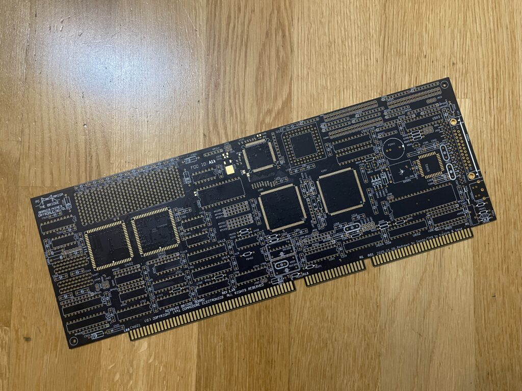
The second card was built without sockets
The second card is exactly the same as the last one, a different color though. This time it is black instead of red. Another difference is that I built it with less sockets this time.
Here is a closeup of the PC system chips.
Here are the PC system chips. Pay attention to the 486 chip. It was marked as a 486-66, probably an error when relabeling it.
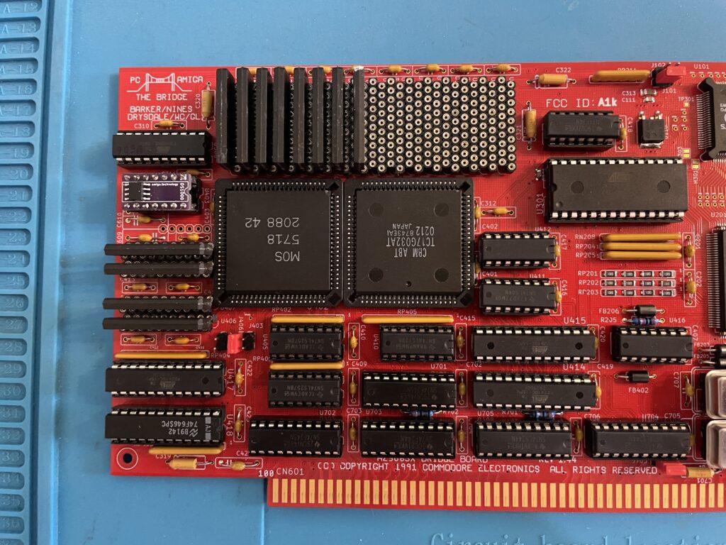
Here are the Commodore chips and the PC memory in the form of ZIP ram (full 8 MB)
And here is the rare 5718 MOS chip and the less but still rare TC17G032AT chip. No PLCC sockets this time!
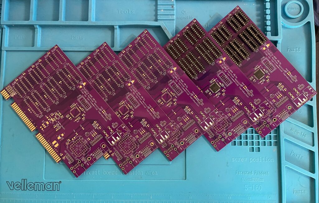
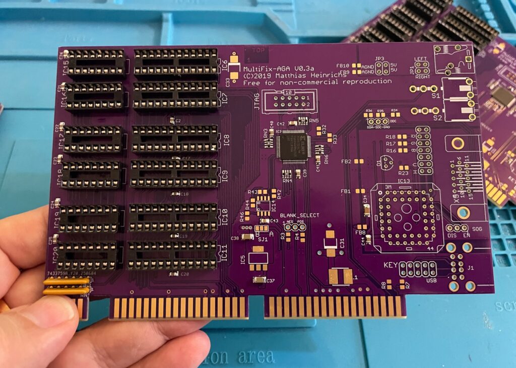
Here are five beautiful Multifix AGA purple PCBs. The Multifix AGA is a great Amiga scandoubler and flicker fixer. I will build two of these and sell the remaining cards once the built cards are tested, or do I build them all for myself (lol).
I plan to use them in the upcoming AmigaPCI (I will for sure build one once it is fully developed) and in my A4000T.
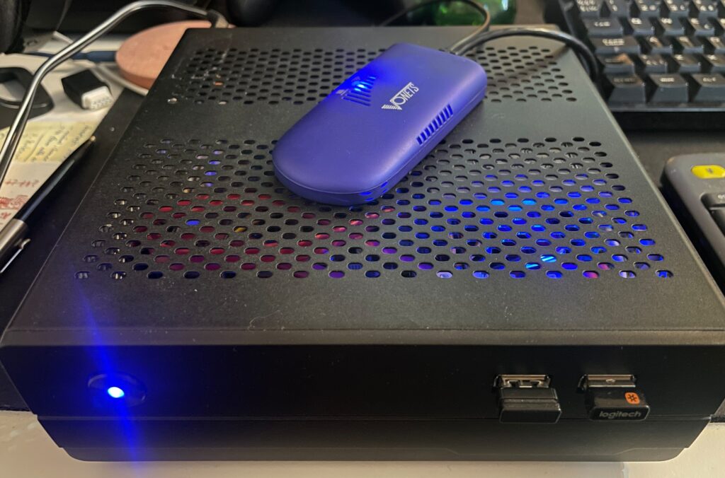
A Sam440EP with Vonets VAP11G-300 ethernet to WIFI bridge
Finally got my Sam440EP that is running AmigaOS 4.1 online with no ethernet cable, wireless, with a Vonets WIFI bridge, no more ethernet cable!!
Currently, I dont have a permanent place for my Sam440EP on my desk at home. That will change in the future. But for now, whenever I want to use it, I set it up on my desk. Since it is a tiny computer, that is not really a problem as its very portable.
But having to run a long ethernet cable between the SAM440EP and the main ethernet switch is such a hassle.
Its not 1999 anymore and WIFI is great these days! So I went looking for a wireless solution for hooking up my next gen Amiga to the home network.
Finding a solution is a bit tricky though. After having spent a couple of evenings researching the topic I decided to order a supposedly supported card by AmigaOS 4.1, only to have it be cancelled by the seller. Disapointed but also relieved because I did not fully expected the card to work – I Instead opted for an ethernet to WIFI bridge.
Thinking, if that works, I could get a second and hook up my A4000TX to the home WIFI network with one also since there is no WIFI card for Zorro Amigas..
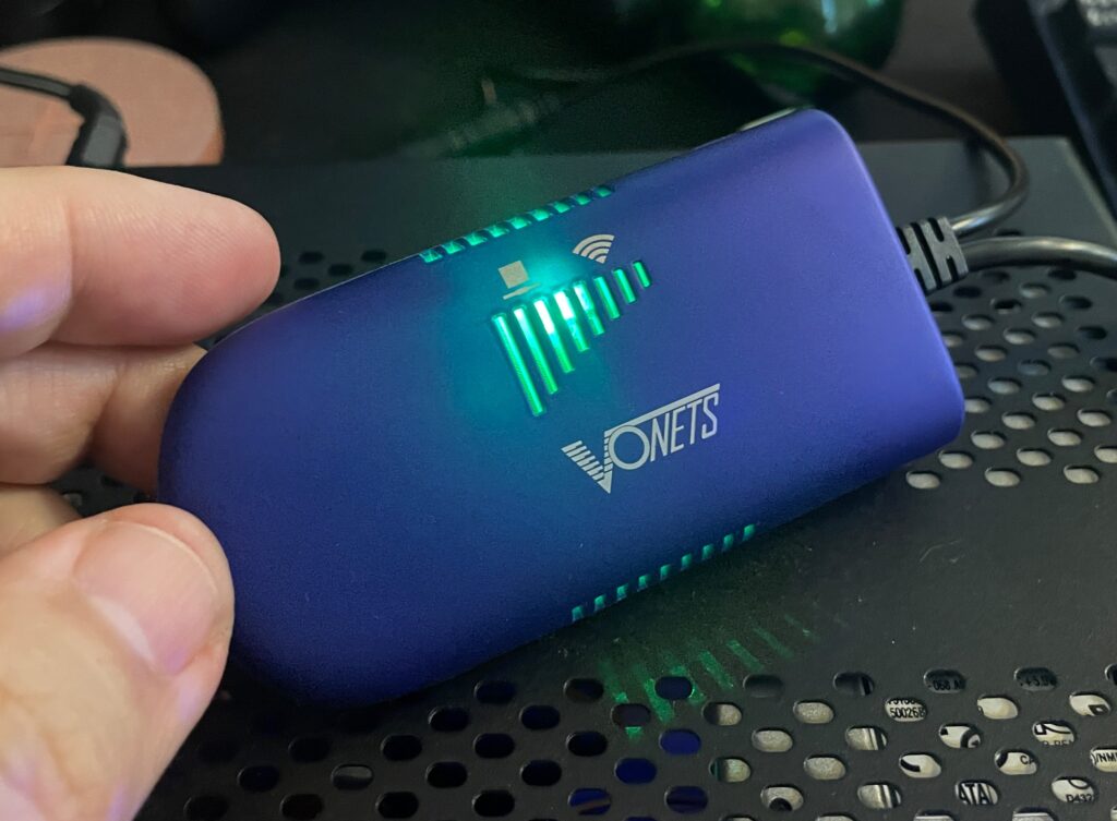
Vonets wireless bridge – VAP11G-300
There are a couple of nice solutions for wireless bridges these days and the prices has gone way down since last time I was in the market (2005). The Vonets Wireless Bridge that I got from AliExpress cost around 20 euro.
Setting up the Vonets wireless bridge on the Amiga
Test setup during initial setup of WIFI on the SAM440EP
Setting up the Vonets VAP11G-300 WIFI bridge reminded me why I chose not to go down the network admin/sysadmin route back in my university years. Or it reminded me of how much simple everything these days usually are to set up.
Surprised I was, it did actually come with a real manual (something I did not expect from cheap China stuff)!. However the manual was a bit poor in quality and clarity, I think it was better if it did not come with one.
Anyways, just so that I wont forget how to set it up, here is how to set up the Vonets wireless bridge to be a WIFI bridge for ethernet:
Connect the Vonets wireless bridge to a PC. Connect both USB and ethernet so it gets power and can be found by the computer.
On the Vonets adapter: Green light should come up (that is the ethernet port), blue light should come up (that is WIFI).
Disable wireless on the computer if active. Else you wont be able to log into the bridge. Make sure ethernet is active and not disabled.
Go to Chrome and type in the IP adress as specified on the device to connect to the Vonets bridge.
Disable AP functionality of device and click save (if you dont want to use it as an AP). Device defaults to both an AP and a bridge if not.
Change password of device and save.
Go to main panel and scan for SSIDs.
Chose SSID, type in password and save.
Reboot Vonets device
It wont be possible to setup the device again on the IP number after rebooting the device. If you need to configure it again you need to reset it with the little button on it.
Once rebooted it should now be possible to browse the web on the PC where the Vonets wireless bridge acts as a bridge.
In theory it will work with any device that has an ethernet port. Read on…
Troubleshooting the Vonets VAP11G-300 WIFI bridge
So this is where the fun began (or not if you belong to the ones who do not see sysadmin/network admin tasks as a fun).
At first it did not work at all on my Sam. But it worked fine on my workstation.
I then figured out that if I changed the internet settings in AmigaOS 4.1 in Prefs and saved the new configuration the internet came to life! I thought I had solved it but as soon as I rebooted or restarted AmigaOS 4.1 then network access dissappeard.
I suspected the problem was that I had to configure the Sam to use a static IP, but that was not it either. However I got to familarize myself with subnet masks and ip ranges again, how much fun!
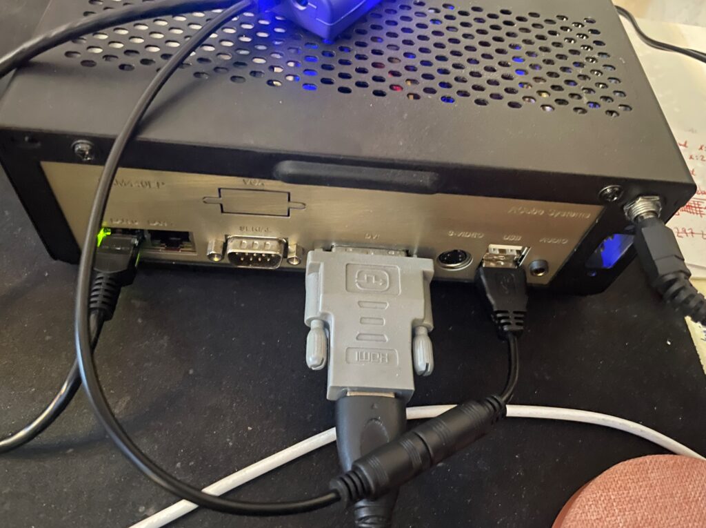
Back of the Sam440EP to illustrate how the Vonets WIFI bridge is set up
Soon I found the problem!
The Vonets adapter takes power from the USB port, the USB port on the Sam is disabled during startup (or delayed) so once Workbench is loaded the network has not fully been initialized. It takes a bit of time for the Vonets adapter to fully start, I suspect it must be running a minimal OS that handles all backend tasks. Which explains why restarting the network works. But until the network in AmigaOS4 is restarted, the network is down.
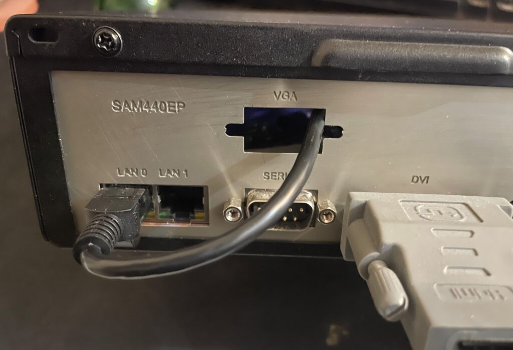
I decided to run it internally by routing the ethernet cable into the case
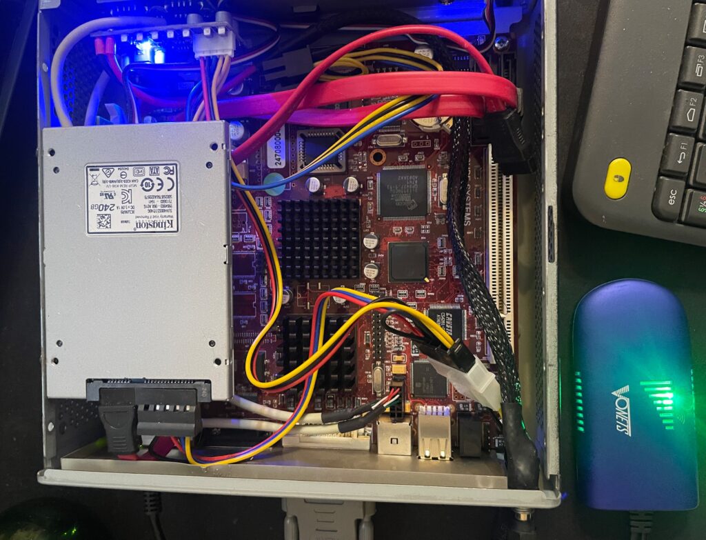
I quickly tried to come up with a solution, the solution was to run the adapter from 5v from the internal PSU. And that lead me to wonder if it was possible to place it inside the case too. I could route the ethernet cable through the hole for the VGA port on the Sam backplate.
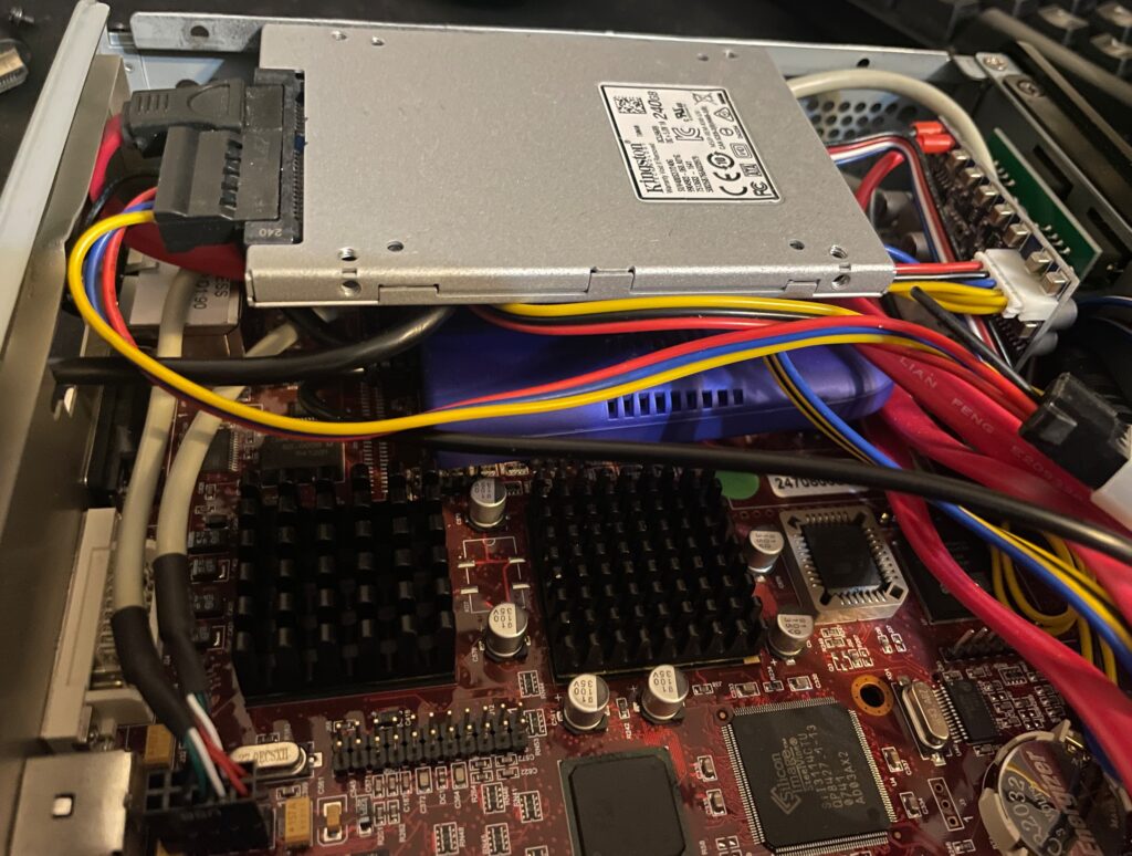
The Vonets adapter is placed under the SSD on the left side of the motherboard
The Vonets WIFI bridge was placed under the SSD on the Sam440EP motherboard. There are no components on that side of the motherboard so no chips will get cooked as the Vonets adapter heats up a bit and I was worried that I would introduce more heat to the system.
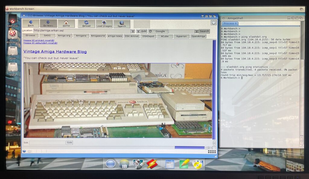
Browsing the web on an Amiga is currently not a fun experience, lets hope a modern browser (and modern hardware is released!)
Would it work, yes it did. The Morex 557 case that the Sam440 is mounted in has mesh sides so signals from the WIFI bridge passes through the case fine (and also aid in ventilation of the setup).
Summary
All in all I am pleased with the setup and will order a second one for my Amiga 4000TX, and my A1200 is already running WIFI with the PicoWyfy. While I am pleased with the setup, much has happened with the web in 15 years. I remember browsing the web back in 2009 on my Pegasos 2 and having a great experience. But the modern web is built on JS and needs SSL. There is no way this 533Mhz system would keep up even if there was a modern browser. While the main goal was not to browse the web but to enable file transfers between fileserver and the Amiga on the local network, I would not mind browsing the modern web on it if there was a modern browser and more up to date hardware.
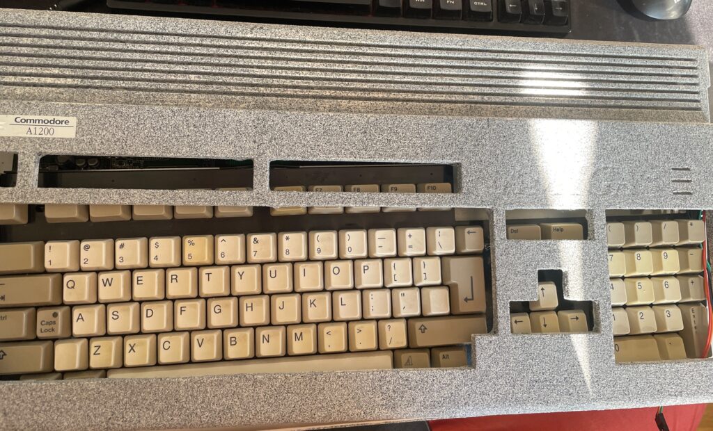
This Amiga 1200 was painted in an unusual color (and paint).
I won an Amiga 1200 on a local auction website. I put in a max bid but surprisingly it got sold for cheaper than I anticipated. I think it was for a couple of reasons. First the case was painted in a weird cement like textured paint, more on that later, secondly it was sold as-is and not working. I have heard of a new Mini-ITX AGA A1200 clone being developed so this broken A1200 will be the donor for that future project (if the chips works).
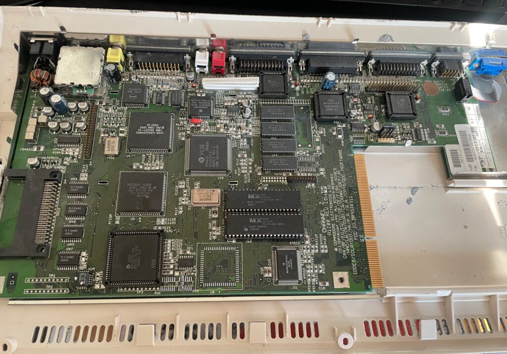
The value in this computer (for me) lies in its chips. I am mainly interested in Alice, Lisa, the two CIA chips and the Paula. I am also interested in the memory chips as those can be used on various projects. There is some value in the 23-pin video socket also.
I did some math and took a gamble on both winning the Amiga 1200 and on the chips working. As the CIA chips, the paula and Alice has been socketed, that is a clear sign someone has messed inside this A1200 before. Could both be good news or bad news as sockets can be the reason for the computer not working.
Anyways, here is how I calculated the value:
Alice: 100-135 euro
Lisa: 20-35 euro
CIA (2x): 35-80 euro
Paula: 25-35 euro
Memory (4x): 10 euro
23-pin D-SUB: 10-20 euro
Total min: 200 euro Total max: 315 euro
Note, I am not calculating this on Analogic prices!
Lets hope the chips are working, will test them later in the year as the motherboard has been cleaned and is archived in my Amiga hardware stash now.
And the reason why i dont count any value in the case: it was sadly painted in this horrible “paint” that gave me a terrible itch in my fingers for two hours after touching it for a few minutes. I will probably throw it away in the trash since I suspect the paint is toxic.
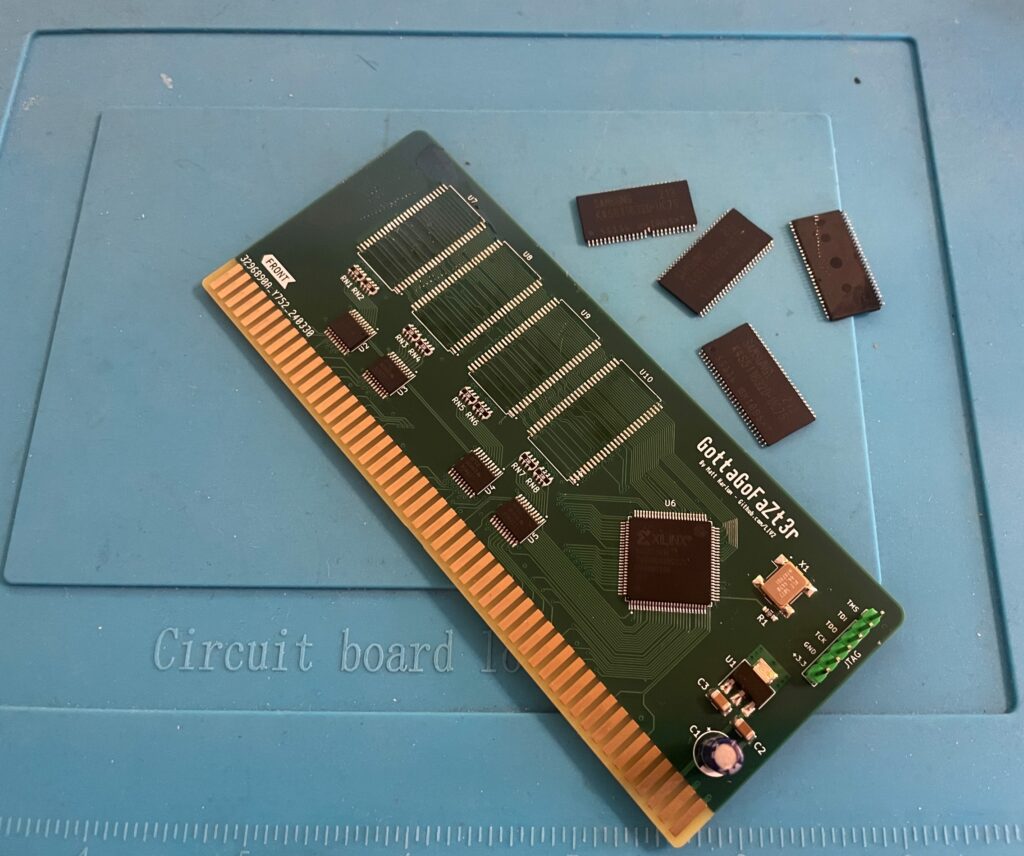
Changing memory chips on a GottaGoFaZt3r
Removing memory chips from the GottaGoFaZt3r Zorro 3 Amiga memory card
I built two GottaGoFaZt3r Zorro 3 memory cards late last year, only one card worked. The other refused to work, it still showed up as “working” in my Amiga 4000TX but the memory was nowhere to be seen. I got the recommendation to check for errors in the memory chips one by one. Instead of doing that I got four new chips instead from a reliable source.
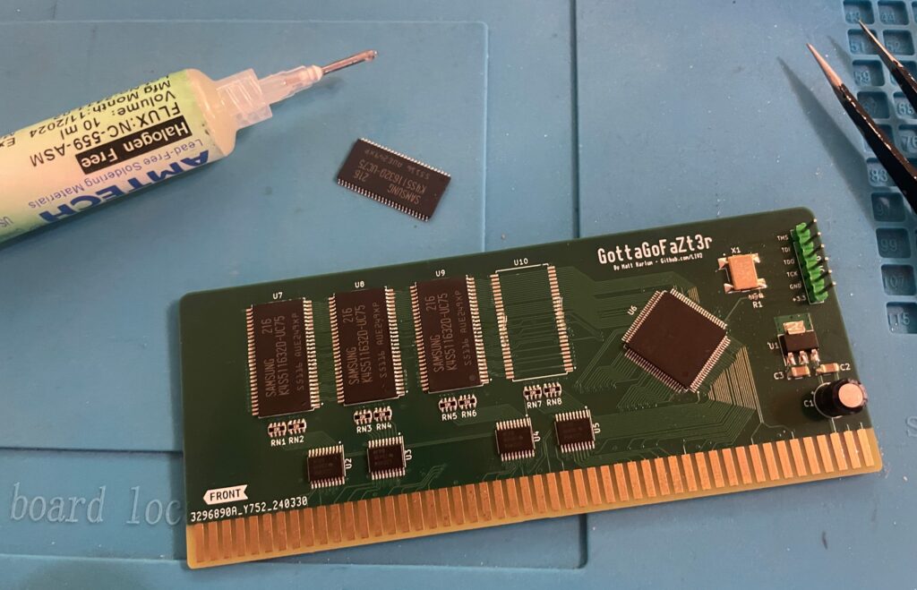
I removed the memory chips with a hot air station. Then I cleaned the pads and soldered on the new memory chips.
Soldering new memory chips on the GottaGoFaZt3r Zorro 3 Amiga memory card
And once all chips was replaced the card finally worked 100%.
Both cards are built as 256 MB cards. 256 MB might seem like a lot of fast mem in an Amiga but it is actually very usable. I run a bit more buffers on my partition than a stock HDD setup so that consumes some of the fast mem. But the main usage is off course to have a large RAM disk (as there are already 128 MB on the turbo card).
And here is a pic from sunny Stockholm today!
Amiga 3000 daughter card
And finally all parts for my ReAmiga 3000 build is now soldered with the daughter board being finished. It still needs to be flashed, but that will happen another day!
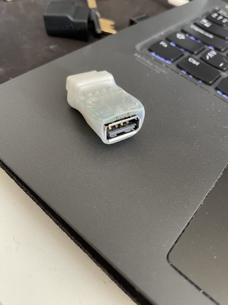
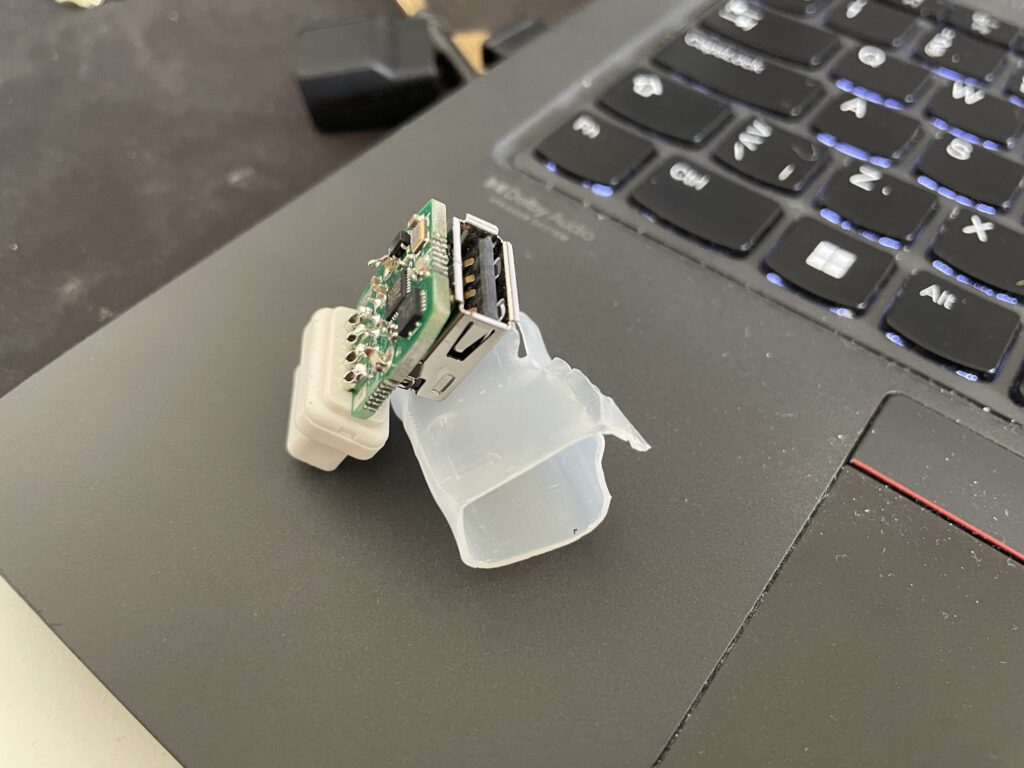
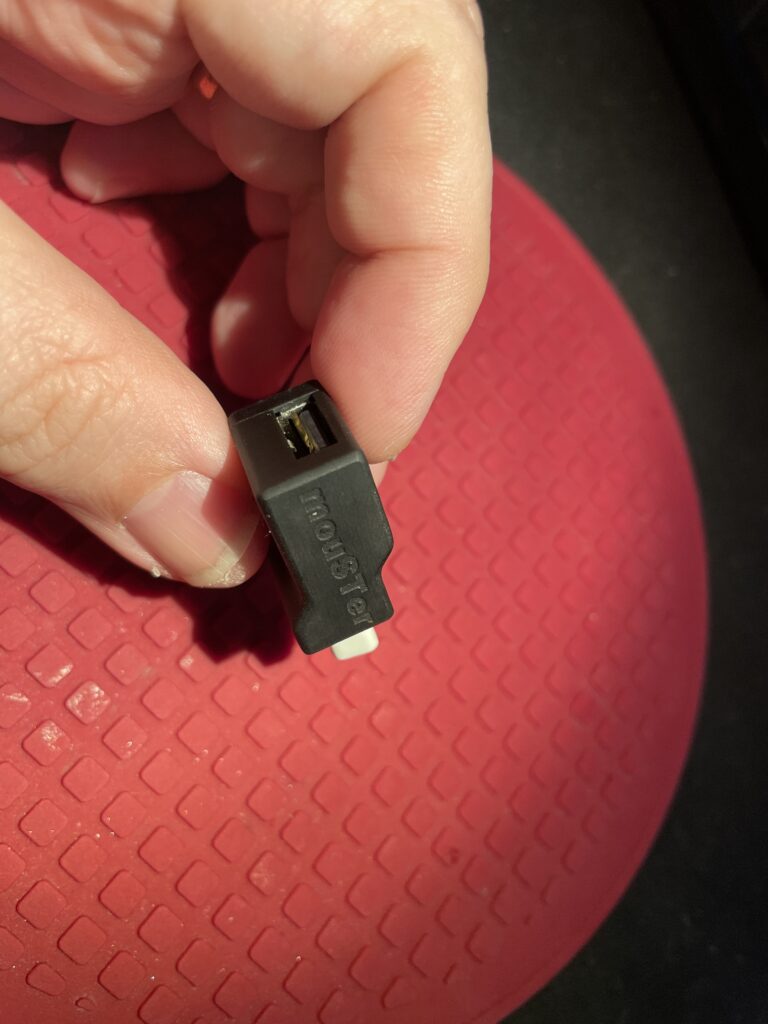
MouSTer 3D printed shell
I have used a MouSTer USB mouse adapter with a wireless mouse on my Amiga for 3-4 years and I have been very happy with the adapter. Only thing I was not happy with was the heat shrink tubing that was used as the shell. It looked so cheap.
I was surprised to find a 3D printable shell for it online. I ordered one to be printed on JLC (in resin). I got a couple of warnings that the walls was too thin and may not be able to be printed. But all worked out better than I anticipated!
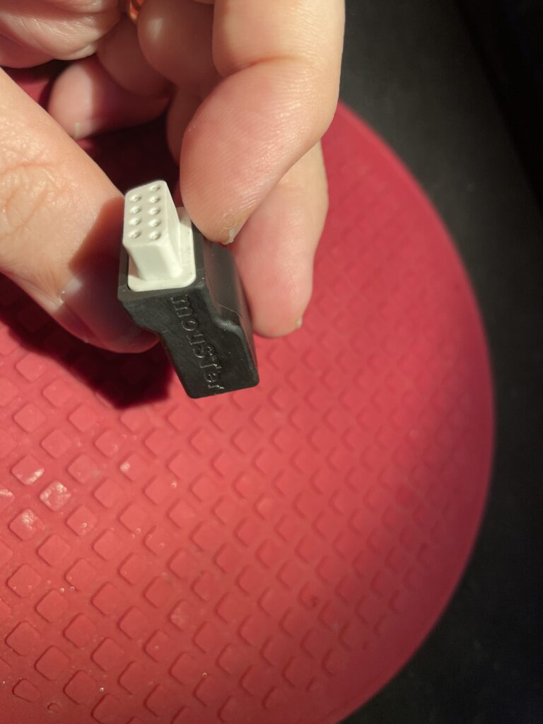
It looks so much better with the 3D printed shell.
The fit is perfect. I just superglued the two halves together, there are no user servicable parts on the MouSTer so no point in making it possible to open the case again.
I dont remember exactly where I found the files but you should probably be able to find them here if you search for them.
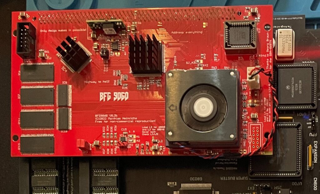
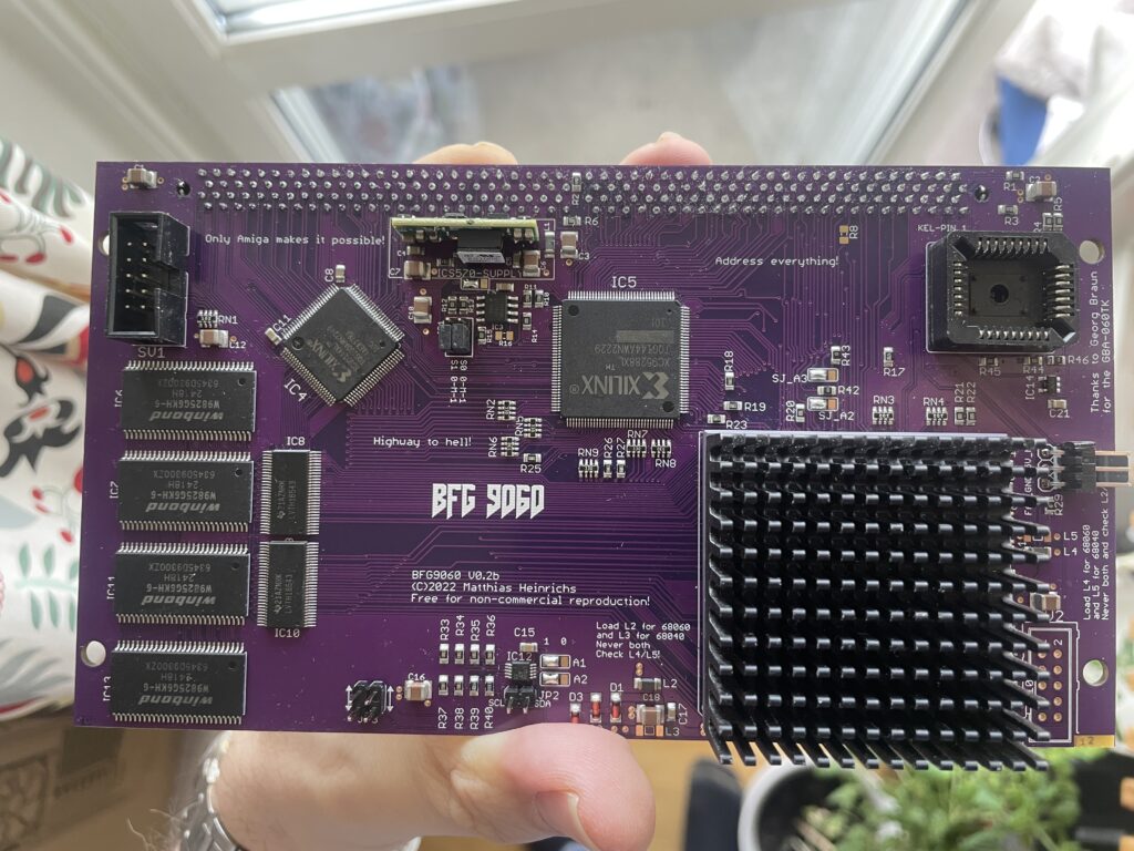
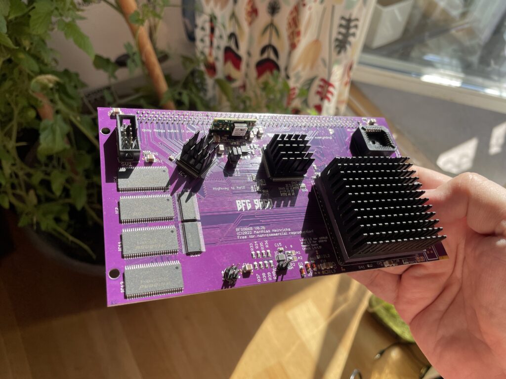
I just finished building this beautiful purple PCB BFG 9060 accelerator card for the Amiga and thought I would share a picture of it. As it was mostly already finished it just took an hour to solder on the KEL connector, fan header and voltage thing (regulator I think?).
I finally get to use the original spec Motorola 040 CPU heatsink that came from an old 040 C= 3640 CPU card I had 20+ years ago. Just have to get some thermal tape, will also add heatsinks to the CPLDs. This card will not be overclocked as it is fitted with a rev 5 68060.
Updated picture of the BFG9060 with heatsinks added
I would like to take the opportunity to thank everyone involved in making this project a reality!
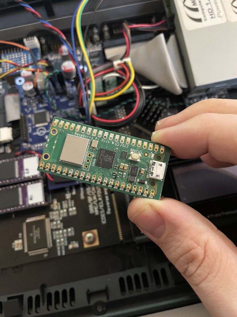
PicoWyfy means wifi for the Amiga hooked up to the clock port!
I just got a PicoWyfy and has spent a day playing around with it in my Amiga 1200. I am very happy with this device as it has helped me get my Amiga 1200 online and onto my network at home.
The PicoWyfy is a “wireless network interface controller” and it connects to the clock port on the Amiga (either on the motherboard or on a Zorro card or other clock port solutions). Read more about PicoWyfy here, you will also find instructions on how to get one there.
Wireless networking has been a possibility on the A1200 and A600 for a long time on the PCMCIA port. I got a NetGear MA401 for this purpose years ago, but the though of having an ugly PCMCIA card sticking out of the side of my Amiga 1200 meant I never bothered to install and configure it. I would rather just put all my files I wanted to transfer on a CF card on my PC and put the CF card in a PCMCIA to CF converter making it easy to copy files of off the CF card to the Amiga HDD.
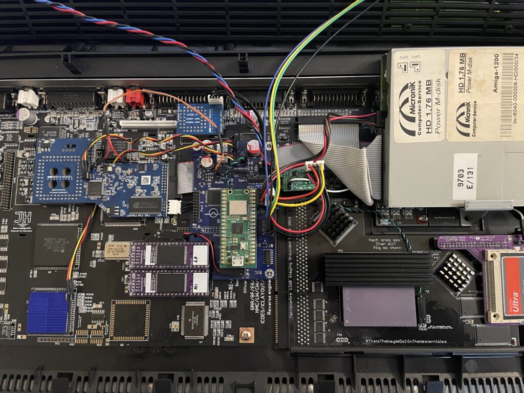
In comparison with PCMCIA solutions the PicoWyfy is placed on the clock port, so it is fully internal. As you can see on the images, the PicoWyfy is based on a Raspberry Pi Pico W.
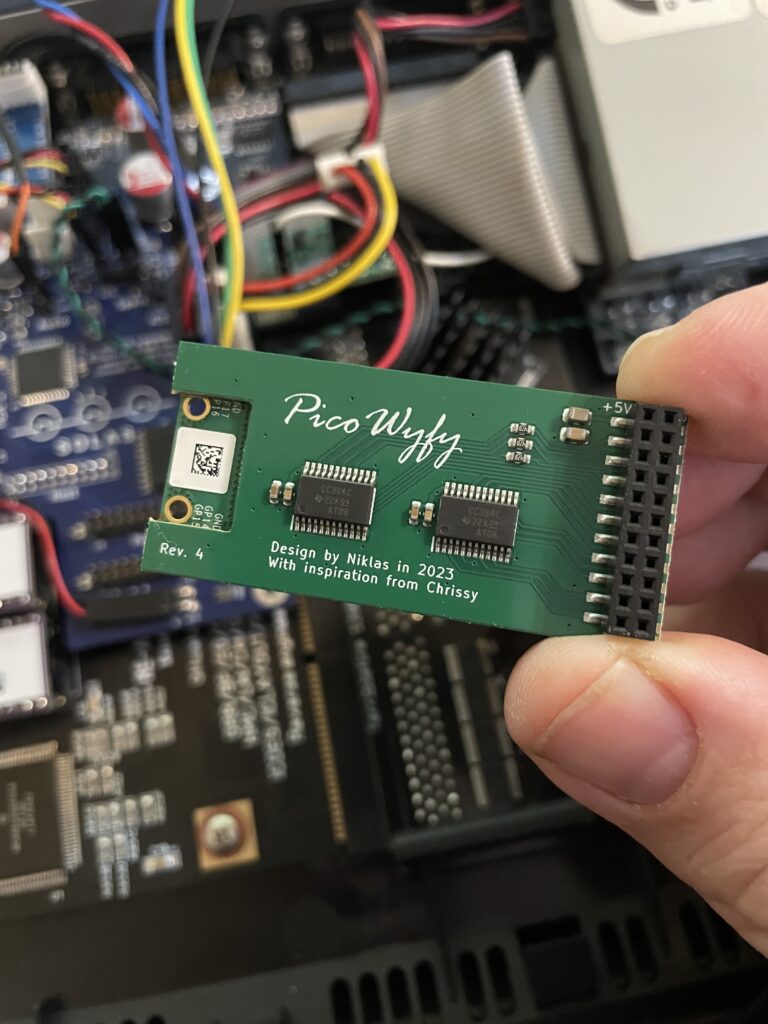
Back of the PicoWyfy card
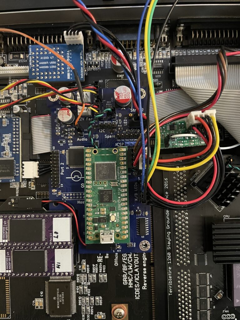
Installing PicoWyfy in my Amiga 1200
PicoWyfy installed on the Solas that is installed on the A1200 clock port
Installing the PicoWyfy in an A1200 was very simple. If you are reading this, chances are that you already know about the clock port in the Amiga 1200 and what to take care of when mounting hardware here. So no point in going through that. If not, I will eat my hat.
My Amiga 1200 already had a Solas RGB LED Amiga controller inside it that was placed on the clock port. The Solas has a clock port expander integrated into it, so installation was as simple as putting the PicoWyfy on one of the free clock ports on the Solas (and configuring the PicoWyfy for that clock port address). Where to put the actual clock on the Solas is another issue I will have to figure out in the future as the PicoWyfy takes up space for it.
Overview of my Amiga 1200 with PicoWyfy installed
As the A1200 case is plastic, there wont be any signal strenght problems. If you wonder what I have in my (main) Amiga 1200, specs are listed below:
ReAmiga 1200 1.5 motherboard
Indivision AGA MK3
TerribleFire 1260 @ 100Mhz / 128MB
FlashROM
Solas RGB LED controller
LED adapter (so that TF1260 IDE activity is seen on the case LEDs)
Buffered CF interface / 4GB CF
MicroniK 1.76 MB floppy drive
And finally, the latest addition: PicoWyfy
Setting up the software and drivers for PicoWyfy
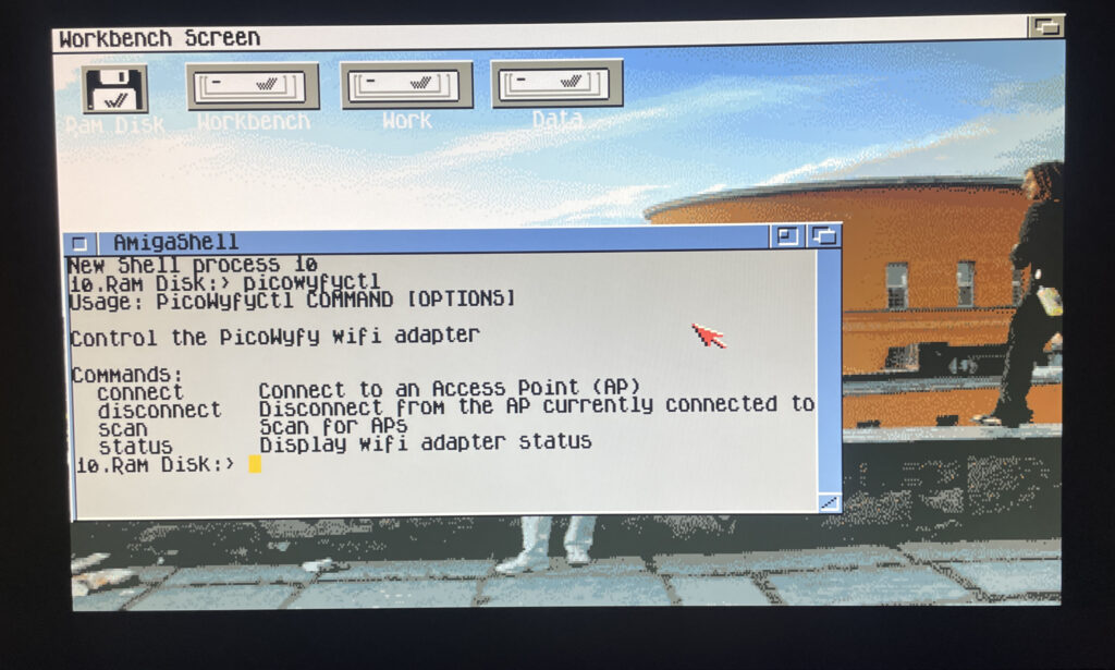
Picowyfyctl is the program that can control the PicoWyfy on the Amiga
Installation of the PicoWyfy is straight forward. All you have to do is put some files in the right places in the Workbench drawer. Then it is possible to run the program picowyfyctl to scan for wireless networks, connect or disconnect to wireless networks and to view status of the PicoWyfy. There is no GUI here but it is so simple to configure you wont need one.
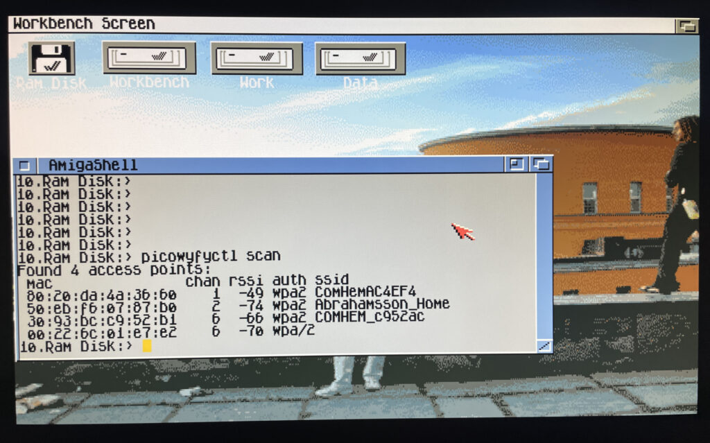
Running a scan on the PicoWyfy to find wireless networks to connect to
In the picture above I have run a scan to look for wireless networks to connect to in my area. I can see my WIFI network here so thats what I am going to connect to.
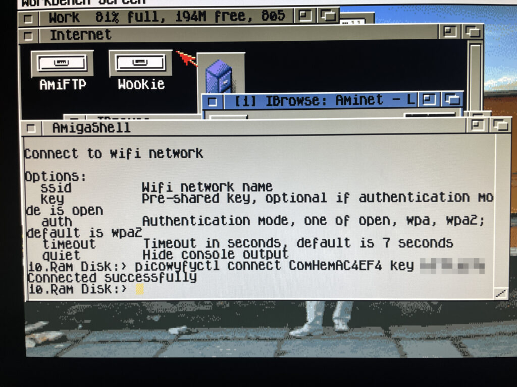
Connecting to a wireless network on the Amiga 1200
Here I am connecting PicoWyfy to my home network and as you can see, the connection attempt was successful! I have also removed my WIFI password, if you must know it is “12345679abcd”.
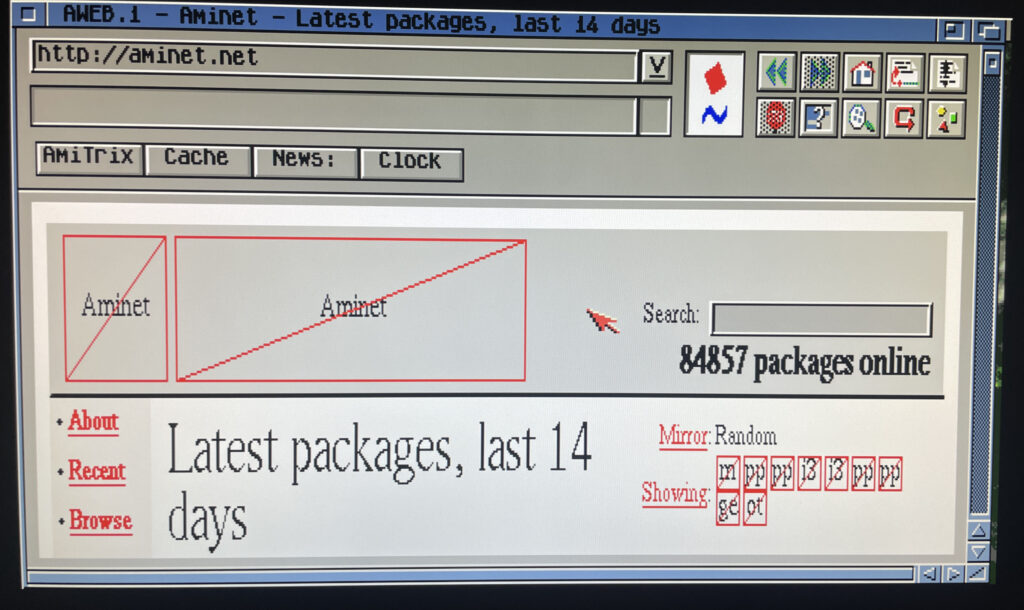
Testing a browser online on the Amiga 1200
Off course I have to test the connection by browsing the information super highway in an ooooooold version of Aweb, if you type something wrong in the URL field it goes to Altavista by default. How nostalgic. As the modern web runs on HTTPS the browsing session was very limited, but I think it is possible to set up HTTPS in some way or another. Possibly would need to investigate this.
But browsing the web wont be my main activity on the A1200 other than browsing Aminet – Having access to Aminet directly from the Amiga 1200 is such a luxury!
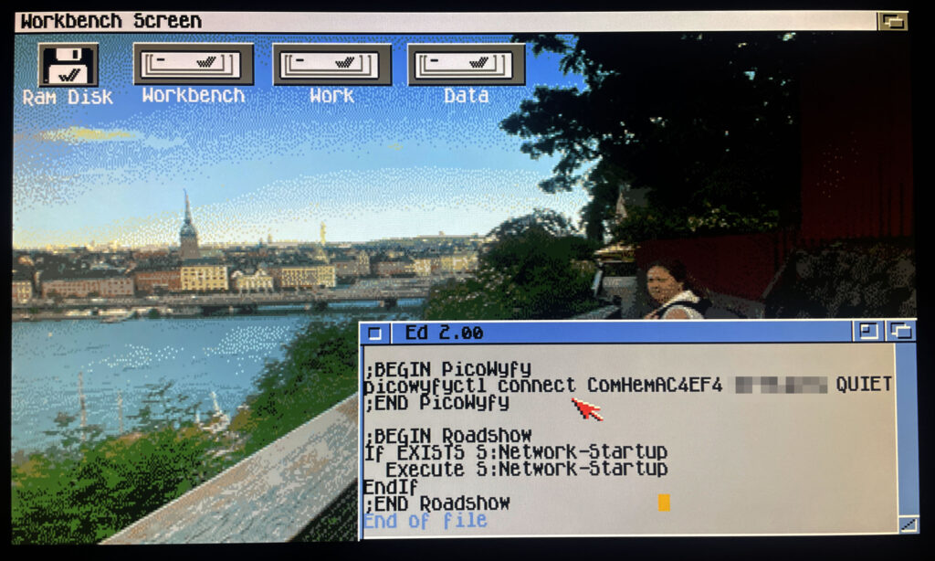
Adding lines to user-startup to connect to a wireless network on startup
I should mention that I use Roadshow as the TCP/IP stack. It is a great modern TCP/IP stack for the Amiga. Once everything was working I wanted my A1200 to connect to the wireless network automatically at startup. To do that it was as simple as adding the line: “picowyfyctl connect ssid key quiet” before the TCP/IP stack was called in s:user-startup.
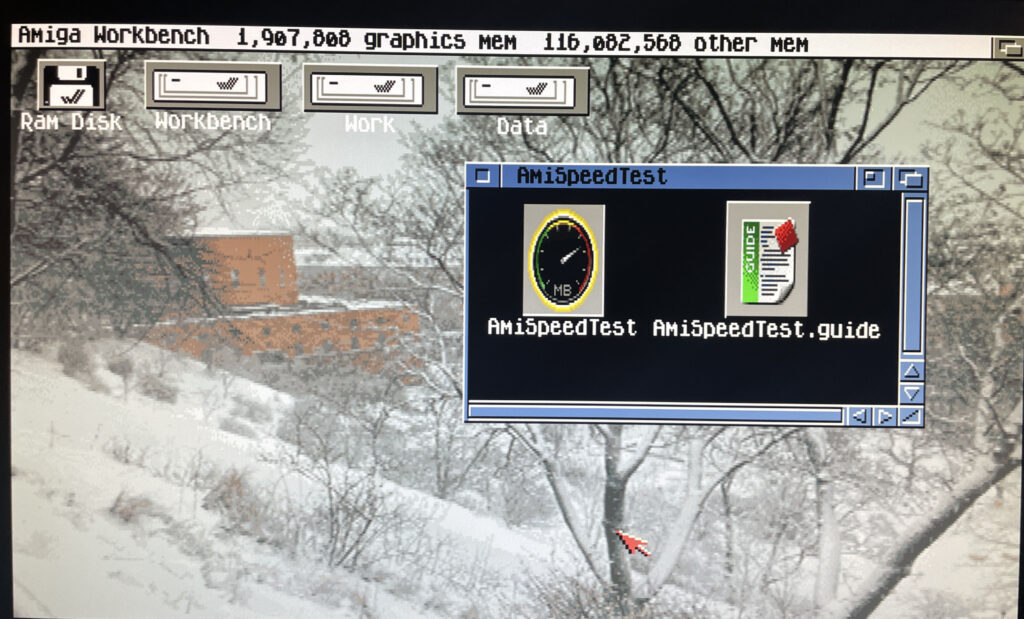
Trying out the program AmiSpeedTest to find out how fast the network is
So lets test how quick the card is on my system. There is a piece of software on Aminet called AmiSpeedTest you can use for this. Here is the URL.
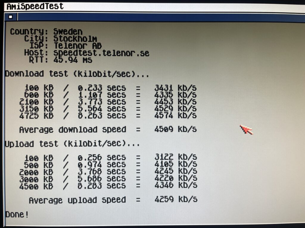
Running a test in AmiSpeedTest
So here is the test done. To be honest here I dont have a clue how good or bad these results are. Downloading stuff from Aminet is fast though so I am happy. Will test some transfers between my workstation and A1200 in the future also.
Average download speed was 4509 kb/s and average upload speed was 4259 kb/s
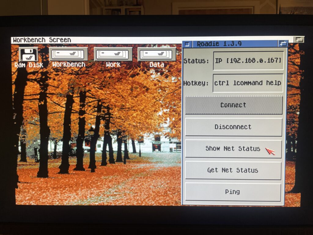
Roadie, a GUI for the TCP/IP stack Roadshow
Before I close off I also want to quickly introduce Roadie, it is a GUI for Roadshow you can find on Aminet. It has come in handy when testing the PicoWyfy and I think this one will go into the default toolbox on all my Amigas. Find Roadie on Aminet.
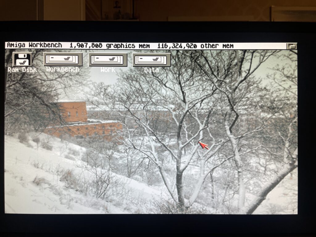
And here we are after a reboot of the Amiga 1200. There is no sign of it but my A1200 is connected to my wireless network at home!
Conclusion
I am very happy with the PicoWyfy, its a great addition to my A1200 and to be honest I would like to equip all my Amiga computers in the fleet with one or a card with similar functionality. Great work everyone involved in this project! Highly recommended!
Typically I like to use wired network, but as the years has passed I think wireless networking is perfectly fine. Even for non mobile computers.
I dont run WIFI on my main desktop workstation, but for everything else, why not, one less ugly Cat 6 cable to pull out everytime one wants to hook up something to the internet.
The reason for wanting to connect an Amiga to the internet or a LAN is primary just to move files to the Amiga. But I have some future plans of having all files centralized on a main server and then sync that share with my Amigas. That way I have multiple backups of my Data folder on all my Amigas while I have a central location that I primary update.