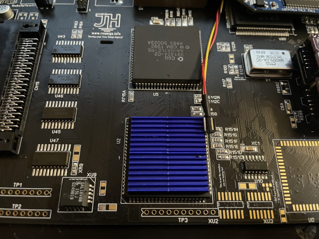
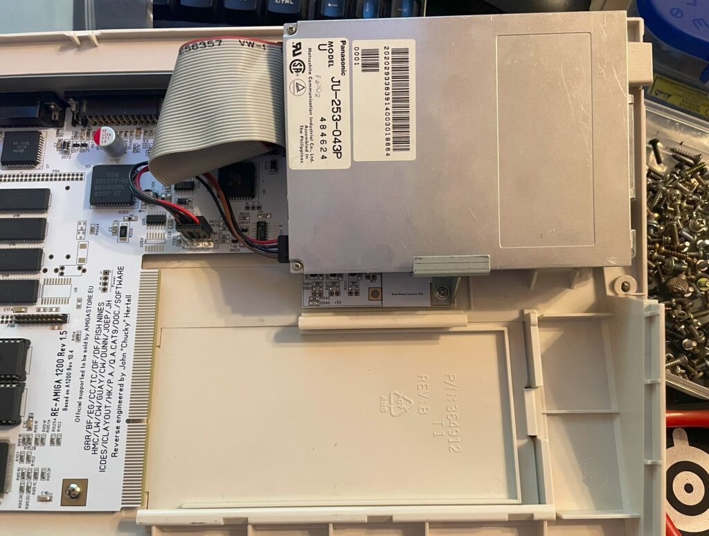
Alice is the graphics chip in the Amiga 1200 and Amiga 4000. It runs hot. The main board acts as a heatsink for the chip so it is not really nesesarry to add a heatsink to the chip. But to help it out with some additional cooling anyways I placed four 3 mm tall heatsinks on Alice (on thermal tape). It still hits 50 degrees, but if I remember correctly, it runs slightly cooler.
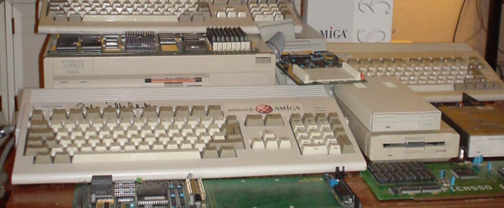
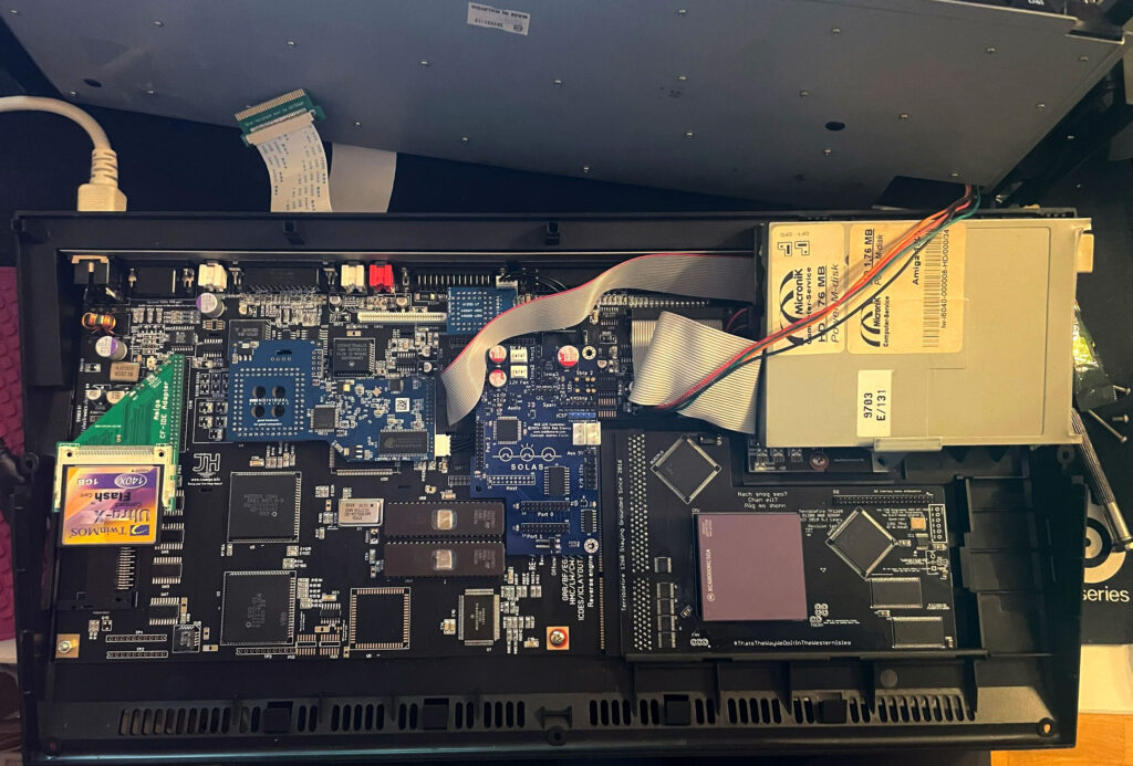
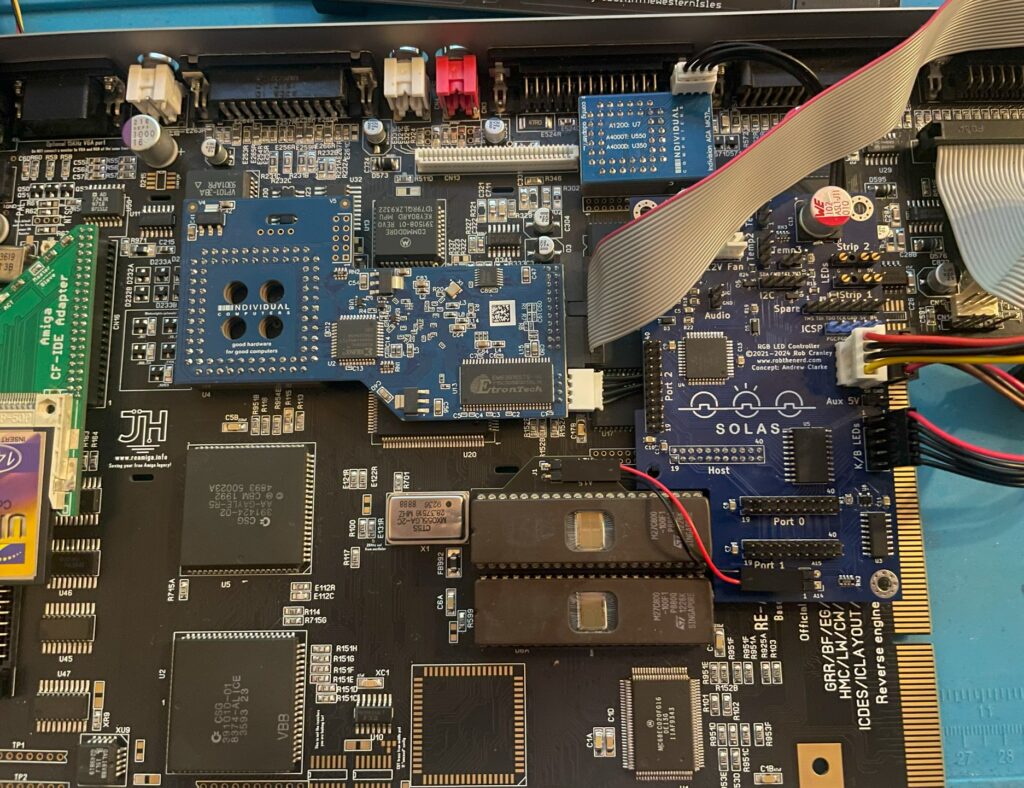
Solas installed in my ReAmiga 1200, it is the blue board to the left of the floppy drive
I have recently been playing around with the highly sought after Solas. The Solas is an RGB LED controller for the Amiga, it also has some other interesting functions. Solas connects to the Amiga on the clock port and can control two LED strips. Solas has also the ability to control fan speed and measure temps. It is also a clock port multiplier!
While I am not very interested in RGB lightning in computers typically the difference here is that the RGB lights can react to the sound the Amiga is putting out. When playing a module you can see the LED strip jumping to the beat of the music. How nice!
I enjoy playing modules on the Amiga and all kind of graphical visualizers for module players are all kinds of awesome. The more the better – I have been thinking of hooking up external VU meters for many years but to have them integrated into the Amiga is much better!
Before we contionue – If you are interested in the Solas board I highly suggest visiting the official Amiga Solas website and ordering one now! These days, good things come in small batches in the world of Amiga and if you dont hop on the train before it has left the station, sometimes it never comes back.
Building the Solas LED controller
I like building hardware myself so I asked if I could get the Solas as a kit, which I could. I also got a second Solas already built, it is a long story why and I wont write it down here to bore anyone. Lets just say, resistors can go bad sometimes and sometimes it can be good to have an oscilloscope in your toolbox (I dont have one).
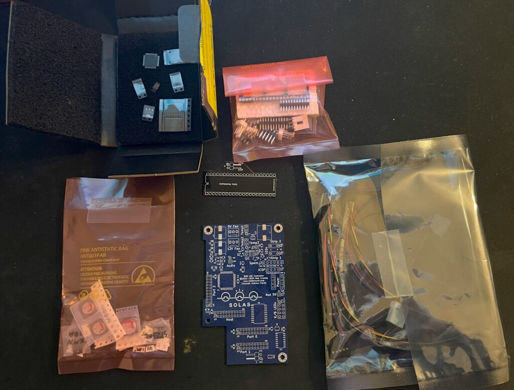
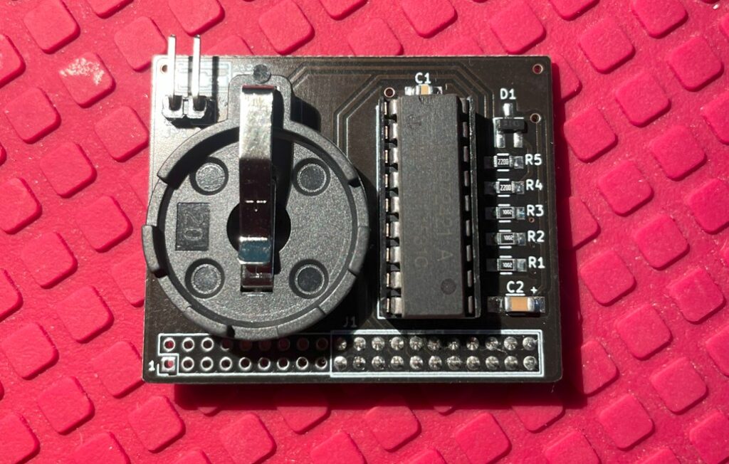
Here is the Solas in kit form. A nice mix of through hole parts and surface mount components. Also note all the cables for the temp sensors and power cable.
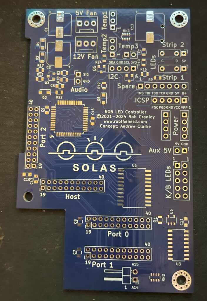
Front side of Solas Amiga RGB LED controller PCB
The square space if for the chip that needs to be programmed. You can also see all through holes for pin headers and clock ports. The manual comes in really handy here in understanding how everything is tied together.
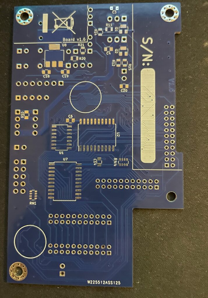
Backside of Solas PCBPrograming the PIC microchip on the Solas
I thought I could program the Solas with my RPI. I have successfully managed to program many projects that uses Xilinx CPLDs with the RPI but was not successful in this case. So I got a cheap Pickit programmer. It is not visible in the image above though but worked fine – setting up the Pickit programmer with the correct software and settings was a nightmare though.
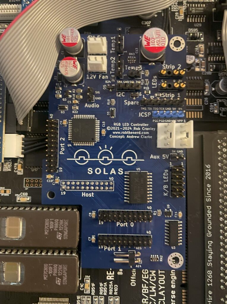
So here is the little PCB finally fully built and installed in the A1200. As it connects to the clock port it is very important that it is fitted correctly on the bottom pins. If you use a cable and mount it wrong way, expect card to break. Why would you mount it on a cable? Say you have an Amiga 1200 tower, it might be better to mount it on a cable so that a Zorro 2 or Mediator backplane can be fitted in the tower. Mounting Solas on a cable is also relevant if you have a clock port in a big box Amiga through a Zorro card.
Next steps, connecting all the cables to Solas and Amiga 1200
Installing and adding cables to Solas in an Amiga 1200
The manual is very good at explaining how you hook up all the cables, it is slightly confusing doing this without consulting the manual trying to figure it out yourself so in this case the manual is a must read (lol). In the image above, there is a small PCB that sits under the upper Kickstart chip and hooks up to the Solas with two wires. That is for activating the other clock ports on the Solas (IIRC).
How to connect sound output into Solas on a ReAmiga 1200?
Pin header for mono sound input to the Solas on the ReAmiga 1200 v1.5
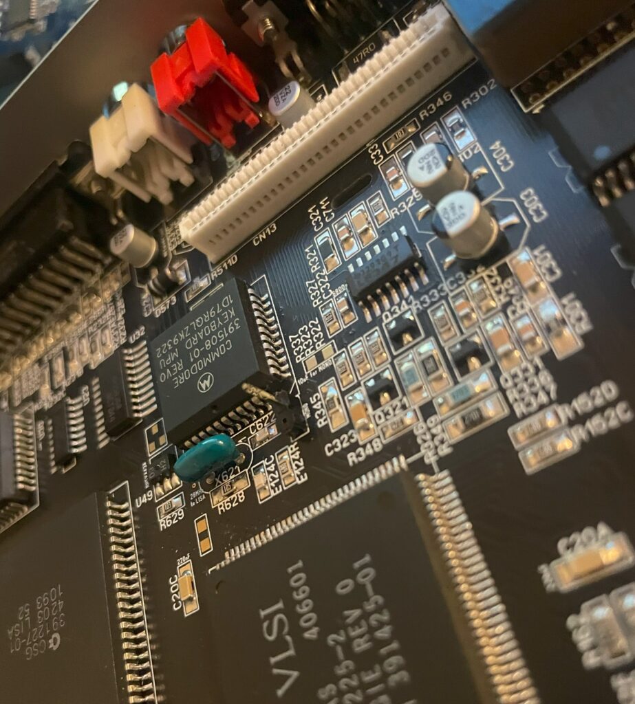
Since I was using a ReAmiga 1200 and not a Commodore made Amiga 1200 there is one difference that needs to be taken care of. On a genuine Commodore Amiga 1200, you can pick up mono sound from the modulator. But the ReAmiga 1200 does not have a RF modulator and is missing the mono output there. On later ReAmiga 1200 (I have v 1.5) there is space for a pin header close to the keyboard MPU chip where you can pick up mono sound (see image above where I have soldered on one pin header to the motherboard). Also note the place above and to the right of the pin header where you have to add a 10uf ceramic capacitor. I have not added the capacitor on the picture above.
To get the Solas to react to sound input I also had to place a 10k resistor inline with the cable connected to the pin header and to the Solas board. After that, everything worked fine!
ReAmiga 1200 with Solas installed
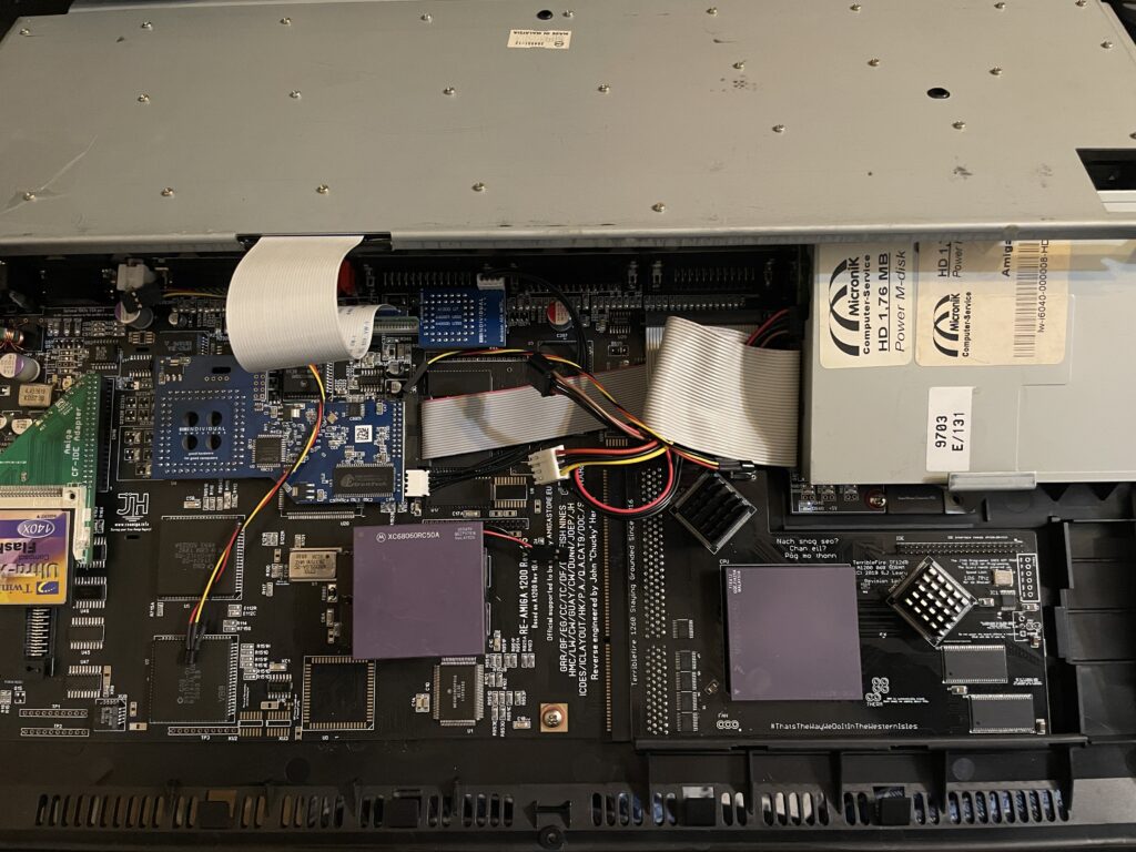
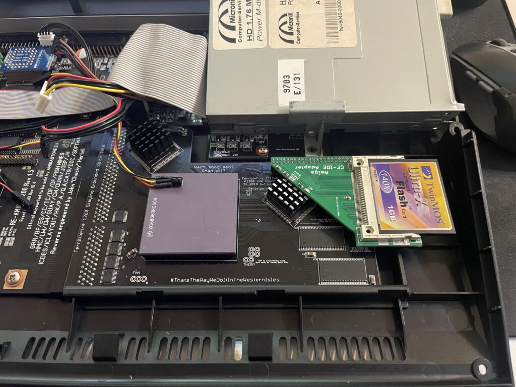
So here you can the full setup. Unfortunately it looks a bit messy with the Indivision, CF adapter and all the cables all over the place. It is possible to clean it up a bit, but for testing purposes this was fine. You can also see where I placed the RGB LED strip. I ended up super gluing the LED strip to the case because the sticky backside was not sticky enough. I routed the cable from the Indivision MK3 under the Solas board, made it look much cleaner and works fine.
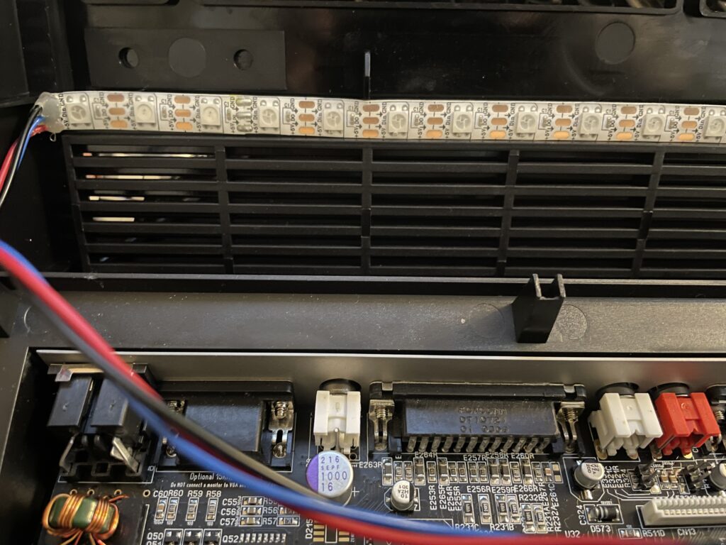
RGB LED strip is mounted to the underside of the upper Amiga 1200 case
Closeup of where the RGB LED strip is mounted. Even though it is mounted upside down in a solid black case it works fine and you can clearly see the light the LEDs are emitting when they are lit.
SolasControl – Software to control Solas
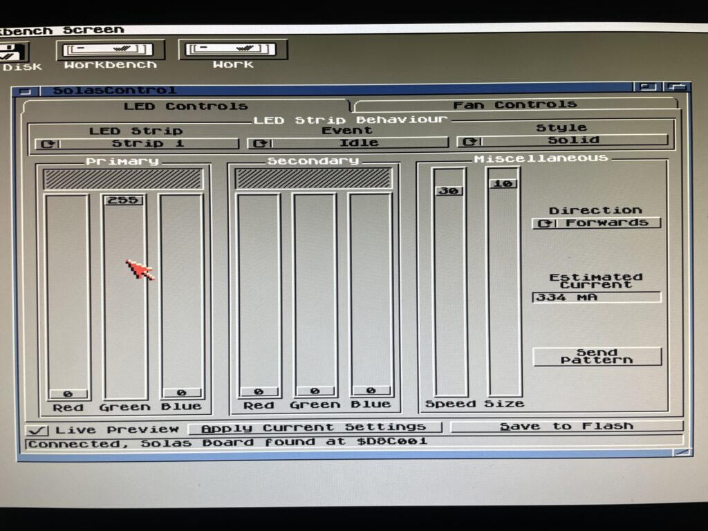
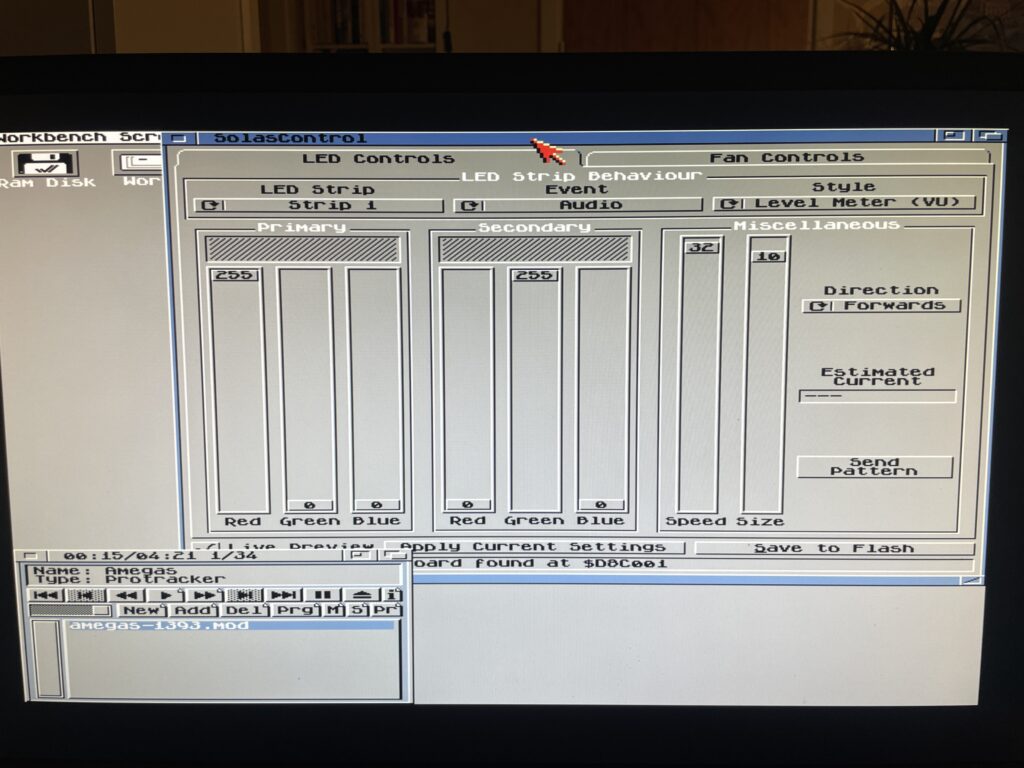
Use SolasControl to configure the Solas board in the Amiga
Solas comes with a great MUI based program that lets you configure Solas. The way this works is that you configure Solas, then you save your settings to the Flash on the Solas. That means that Solas will work with software that fully takes control of the Amiga.
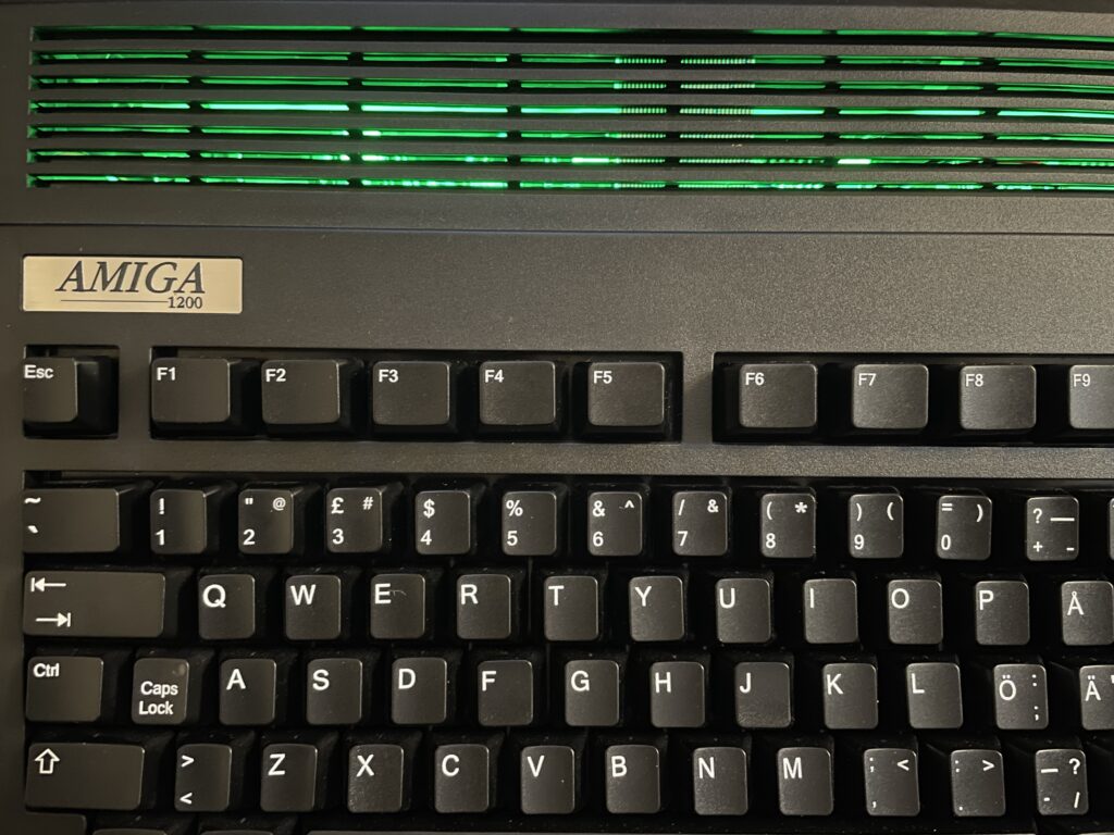
SolasControl is an easy to use program, in the image above I have configured Solas to show a solid green light when the Amiga 1200 is idle. It looks like this:
Solas configured to show a solid green color when the A1200 is idle
Solas styles and events
As you can see on the image of SolasControl, you can set the level of brightness for the LED and in the highest strength the LEDs are very bright. I usually do not run the LEDs at the highest brightness.
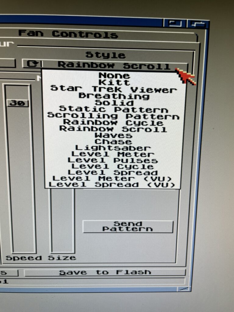
Styles you can chose from in SolasControl
A static color is a bit boring. There are many styles you can chose from, my favorite is a rainbow scroll with a low brightness setting when idle. See the video below to see an example of it where I chosed blue and red as colors for the scroll.
Speed, colors, brightness and size depending on style chosed can be configured to ones preferences.
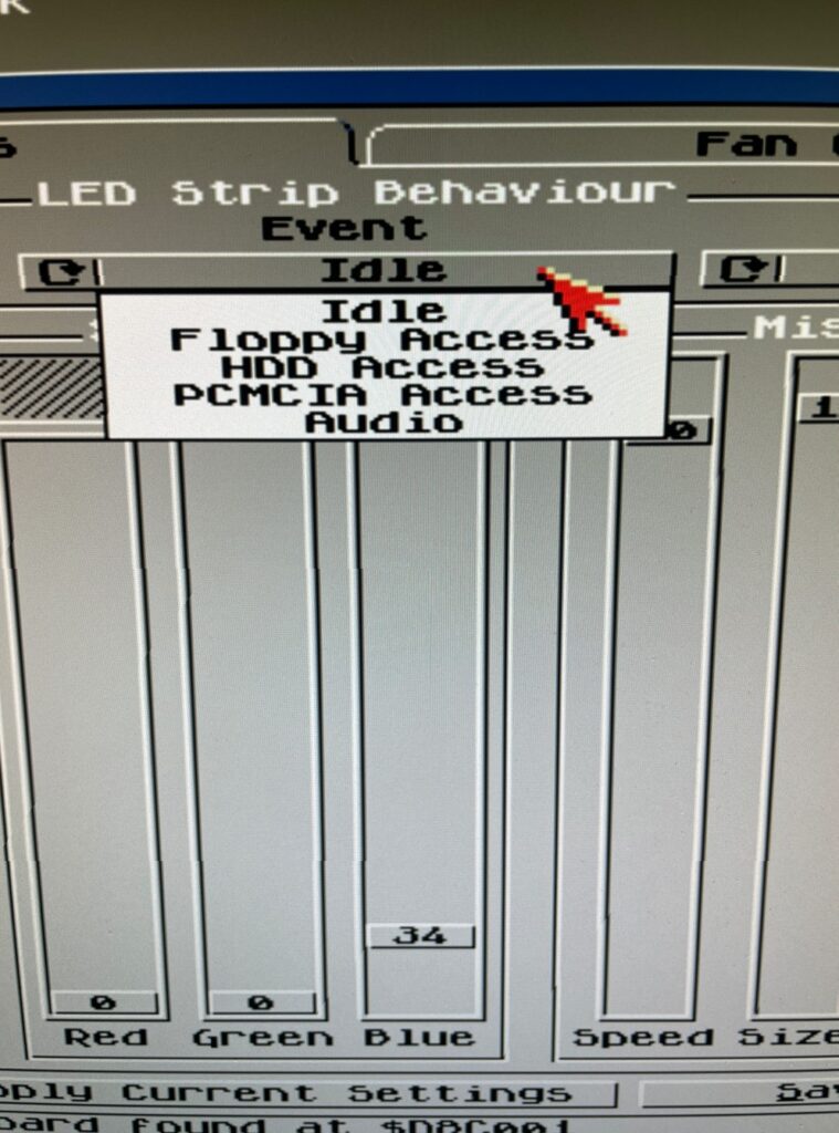
There are in total five types you can set the Solas to react to, Idle, Floppy access, HDD access, PCMCIA access and Audio. Idle just means when Solas is idle (when the other types are not active). Audio is when there is audio output and floppy/HDD and PCMCIA is when there are activity on these devices.
I like to run Star Trek Viewer for HDD Access, its a nice effect when accessing the HDD. I also as said before run Rainbow Scroll with a low brightness setting when idle. And finally, the pièce de résistance, audio. I like Level Meter (VU) for audio!
RGB LEDs reacting to Amiga sound
Playing a module in HippoPlayer on the A1200 and watching the RGB LEDs react to sound
I want to point out that I usually run a little more fancy Workbench (even on this non GFX board AGA only Amiga 1200 WB 3.1), but in this case I toned it down a lot to clarify images.
In the image above I play a module in HippoPlayer, I have also configured Solas to show Level Meter when sound is playing. And I think it looks fabulous!
This is actually why I think the Solas is so exciting since I wanted a hardware device like this for the Amiga for a long time. I remember looking for similar types of hardware on AliExpress more than 15 years ago that could be added to a 5.25 bracket back when I had an Amiga 1200 tower. But this is so much better since it can be configured on the Amiga!
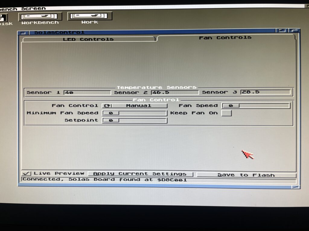
What about controlling fans and measuring temps with the Solas?
Solas comes with two sensors you can place where you want to. I placed one on my Indivision (as it runs very hot) and the other on Alice as it also runs hot. It is possible to add a cable between TerribleFire 1260 and Solas to measure 060 temps, but I have not had time to do that yet, but thats on the todo list.
The fan control function is very interesting particularly if using the Solas in a big box Amiga with many Zorro cards and hot CPUs. I think this is a nice alternative to CPLDIcy.
Usefulness of more than one clock port?
There are exciting developments in the Amiga hardware world where some users have created clock port based WIFI cards for the Amiga. There are sound cards for the clock port and USB cards. So having more than one clock port can actually be usefull – who knows what type of hardware will be released for it in the future. Having a couple extra feels great for the future.
Solas and big box Amiga computers
It is possible to add a clock port to a big box Amiga with Zorro slots through an old Buddha card, ZORRO-IDE-LAN-CP card and many other cards. That makes it possible to run Solas in an A2000, A3000 or A4000.
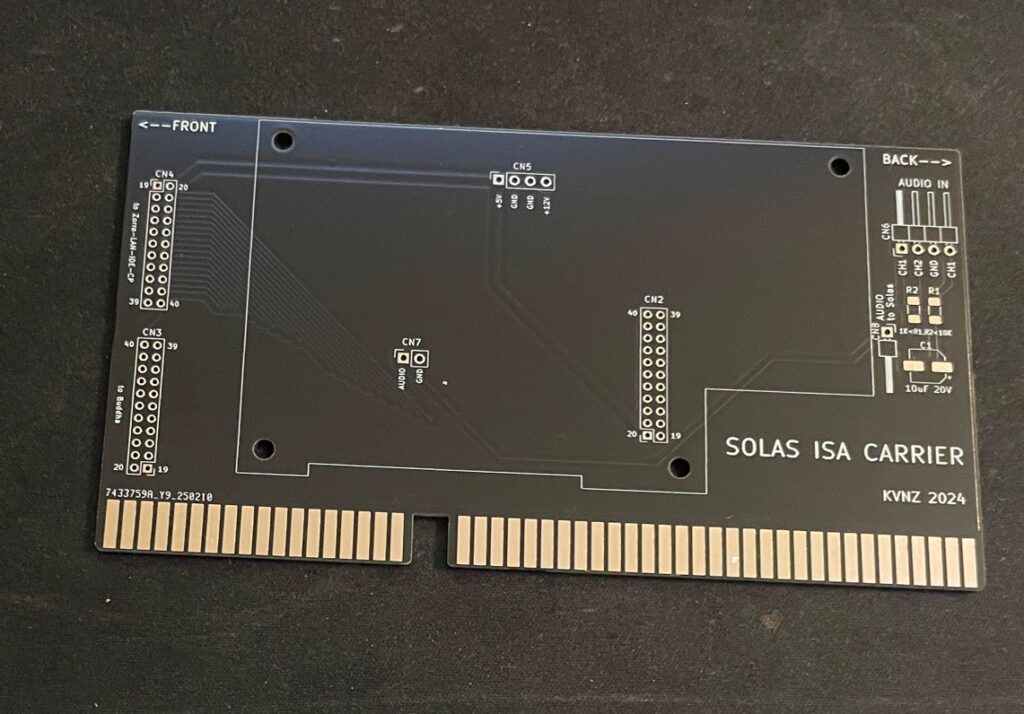
Solas ISA carrier
There is also this exciting ISA card that functions as a carrier for the Solas. As you probably already know, ISA slots in an Amiga are totally passive, meant to be used for PC bridgeboards or TBC cards. so the Solas ISA carrier only provides power to the Solas. It has some useful pin headers though.
Solas mounted on the ISA carrier
Mounting the Solas to the ISA carrier board needs a slightly modified Solas card. One also needs to figure out how to connect sound to the Solas. I figured out that I can take it from pin headers on the ZZ9000 graphics card I am running in my Amiga 4000TX.
How I got sound input into the Solas from the ZZ9000
So here is how I hooked up sound input from the ZZ9000 graphics card to the Solas. Unfortunately the picture is a bit grainy but you get the point, L/R goes into the Solas ISA carrier. Also, it is a temporary cable as only two wires are needed.
Here is how the Solas is connected to the clock port of the Zorro-LAN-IDE card
And here is how the Solas is connected to the clock port on the Zorro-LAN-IDE card.
Keep in mind though if you have maxed out your Amiga expansion slots (we are all Amiga snobs left in this hobby right?) this sandwich of the carrier card and the Solas can be difficult to fit as it takes up more height than a regular card – And even more height with the cables connected to it!
I should also show you the LED setup I am running, I am running two LED strips on the inner sides of the front of the case. It looks awesome when playing tunes.
Final thoughs
As you can probably tell, I have only positive things to say about Solas. Highly recommended! I also think the Solas board is one of the greatest hardware developments for the Amiga in recent years (together with PiStorm and open hardware such as BFG and TF series of cards). Great work everybody involved with it 👍
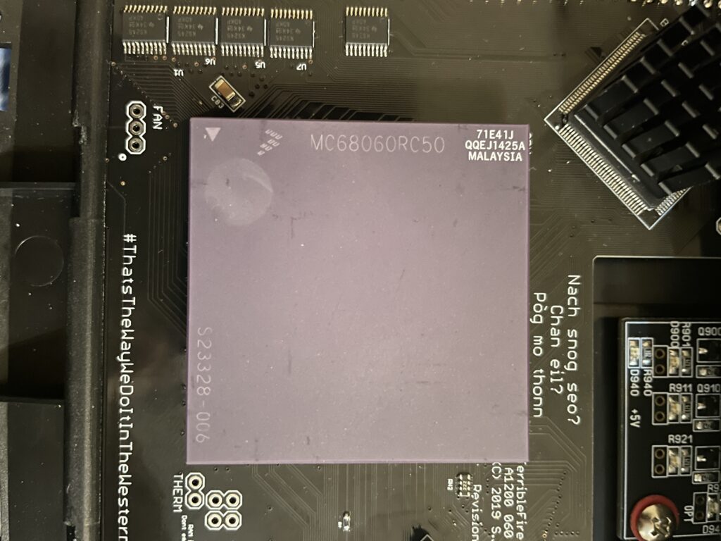
I bought a 68060 revision 6 (71E41J) recently for a very good price. The rev. 6 CPU can usually do a really good overclock, often reaching 100MHz or more, which makes them very sought after and sometimes fakes are offered as the genuine version of the CPU. As I was already running an 060 in my Amiga 1200 I was not sure if it was worth swapping CPUs to gain more megaherts. The rev. 5 68060 I was running could do a 66MHz overclock but ran very hot. And a 50MHz 060 is not a slow CPU (in the world of Amiga).
Swapping 68060 CPUs in my Amiga 1200
I decided to swap CPUs because I wanted to test performance of an Amiga without a graphics card but with a fast CPU and high resolutions (like HighGFX and highres laced). Luckily removing the CPU was not a difficult task, prying on the corners of the socket it was out in less than 5 minutes ready to go into another one of my systems. Once the rev. 6 CPU was inserted into the Terrible Fire 1260 I was eager to do a test. Sure enough, it did not complain anything running at 100MHz!! (keep in mind I had a heatsink on the CPU when doing tests). Next time I will try 106MHz!!
Is there actually a noticeable difference between a 50 and a 100 MHz 68060?
Would I be able to detect any difference between a 50MHz 060 and a 100MHz 060 or would it only be noticeable in a benchmark program?
I was not too sure – When I had overclocked my 060 in my Amiga 4000TX from 50 to 100MHz I could feel that icons loaded faster, drawers just popped up, Workbench was just smoother and more responsive. But I was not sure if it was my imagination or reality.
With that said, I was surprised that my 100% non scientific mean of measuring the difference between a 50 and a 100MHz CPU in the following AGA Amiga Workbench screenmodes highres, highres laced, HighGFX @ 1024×768 (all screen modes in 64 colors) proved that there really was a difference!
Workbench had become even faster and more responsive. Running 3.1 with the stock Commodore 4 color icons, icons did not load anymore, they just popped up, almost all at once, drawers opened up instantly. The system speed by at such a high rate I had only witnessed something like this in WinUAE. What an amazing experience!
I changed background colors to 256 colors and could sense little to no slowdown from a 64 color screenmode. Sure, I have to test this more, but the early results are great, this is what base level Amiga should be like! Lets bring on 200MHz 060 (lets crowd fund it lol).
Cooling problems
Before I permanently run this computer at 100MHz I have to figure out a good cooling solution for the CPU. This rev.6 68060 runs cooler than the old rev. 5 I had in it before. But overclocking it makes it run slightly hotter. I suspect its above 50 degrees but not more than 60. I have some ideas on how to cool it down but will have to sleep on the ideas a little more before I pull the trigger on the stuff I need to build one..
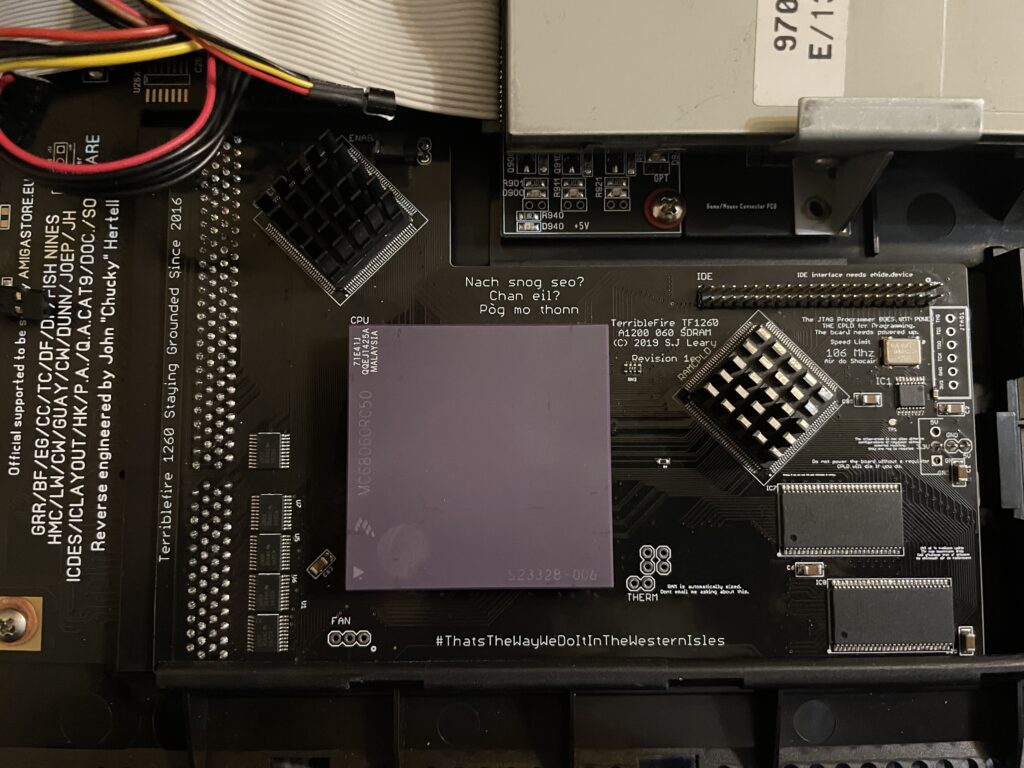
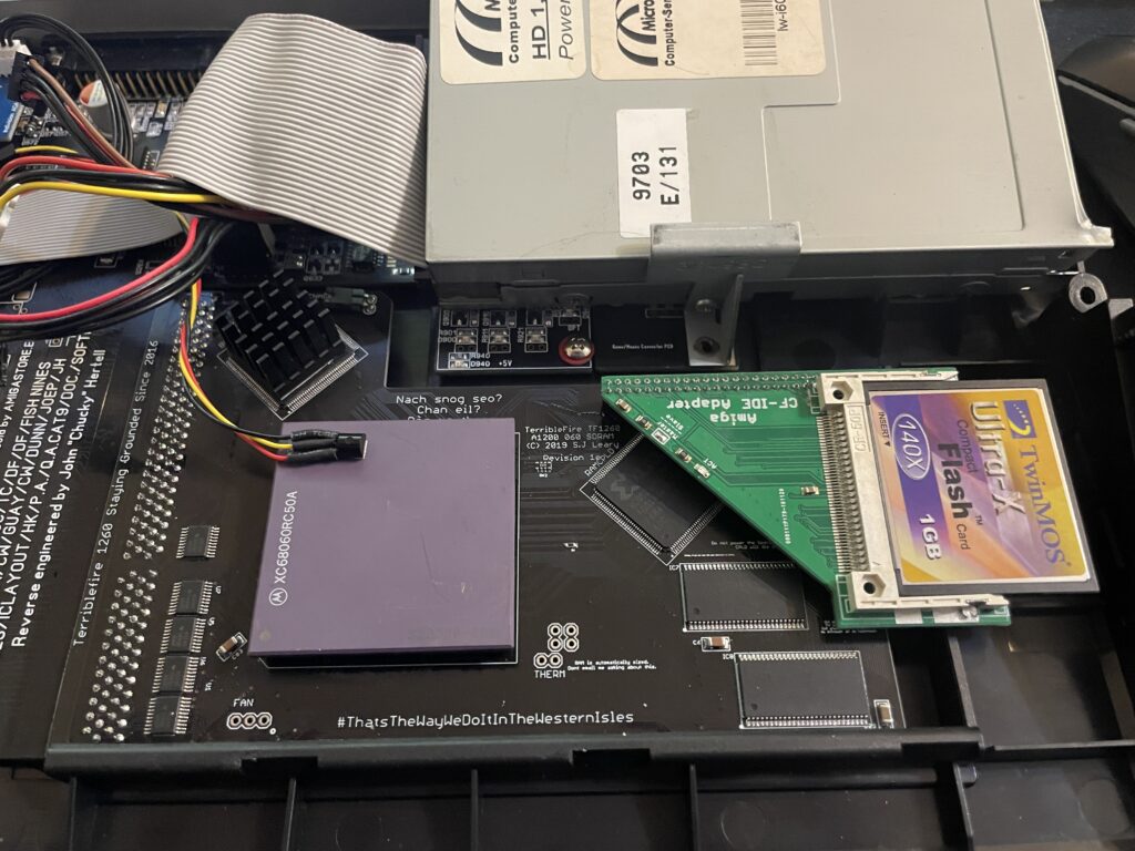
I have a Terrible Fire TF1260 in my Amiga 1200. I used to have an Apollo 1240 upgraded to 060 in it and was very happy with that card (despise what other said about the card, it was very stable for me). Time marches on though and the TF1260 started to look more and more impressive, so I built one last year. The TF1260 supports overclocking by software. One comment I read was that the chances of a good overclock improved if you put heatsinks on the two CPLD chips.
Keep in mind that I had a heatsink on the 060 when doing overclocking tests. But the space between the 060 and keyboard is so tight it was very difficult finding a heatsink in my stash that would fit with the keyboard installed. I have actually not solved this yet, thus I just focused on the CPLDs and will try to solve the 060 heatsink some other day, until then it will run at 50Mhz.
The problem with the CPLD cooler is that the right CPLD need a short heatsink if you want to run a compact flash adapter over it. As you can get an impressive speed boost for the CF card by using the IDE port on the TF1260 this was off course something I would need to consider.
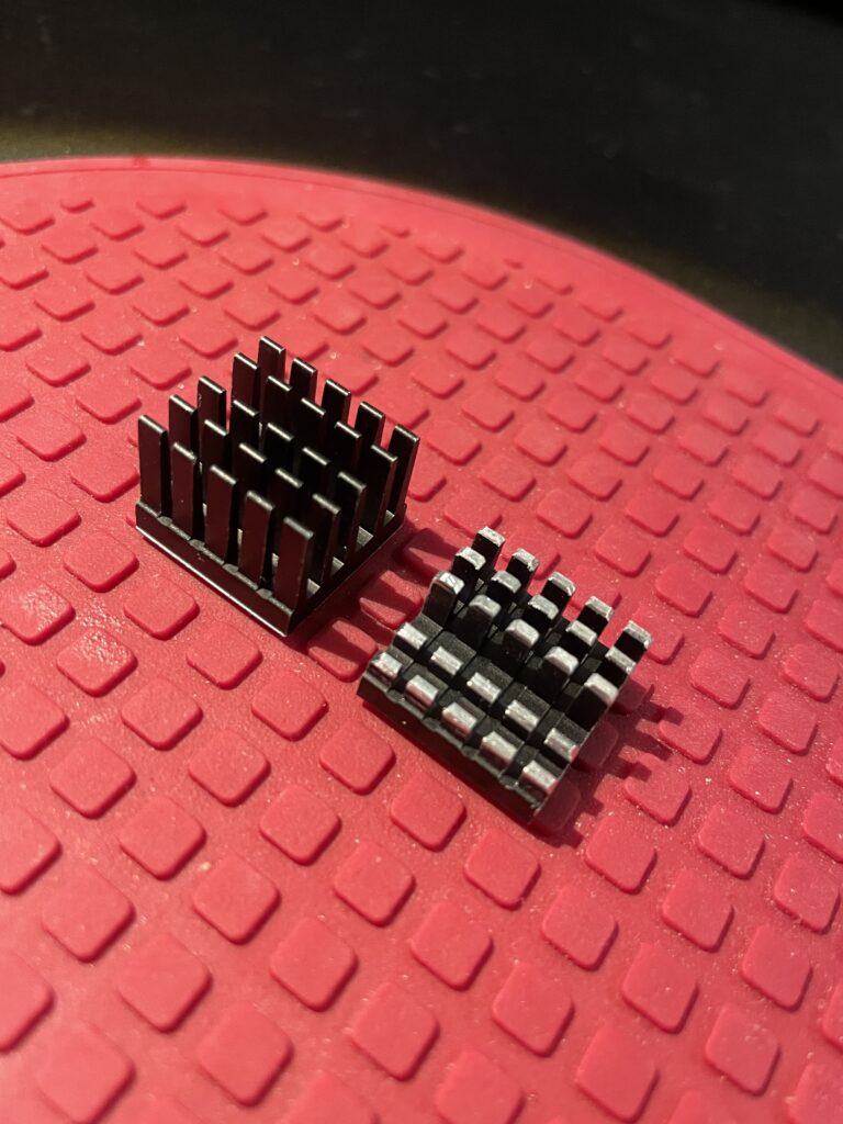
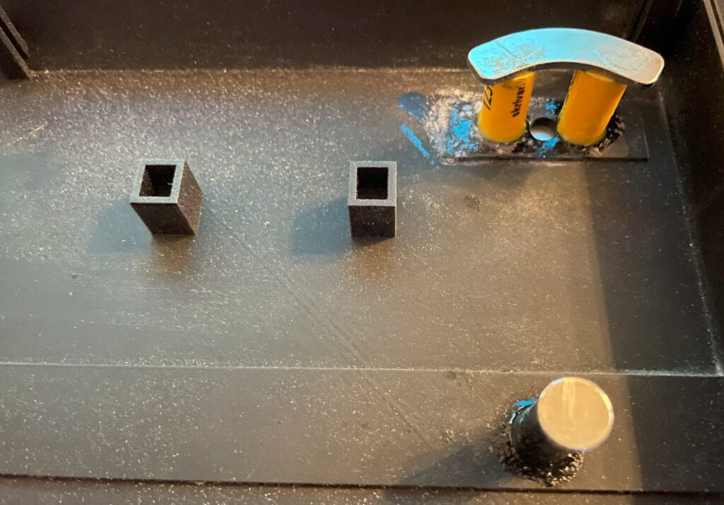
I had ordered these 18x18x20mm heatsinks for this exact CPLD before. The left one is the original form and the right one is the heatsink cut down and modified. I dont like to do fabricating as it gets so messy and difficult to get good results with hand tools. I will probably order a new heatsink in the correct height in the future.
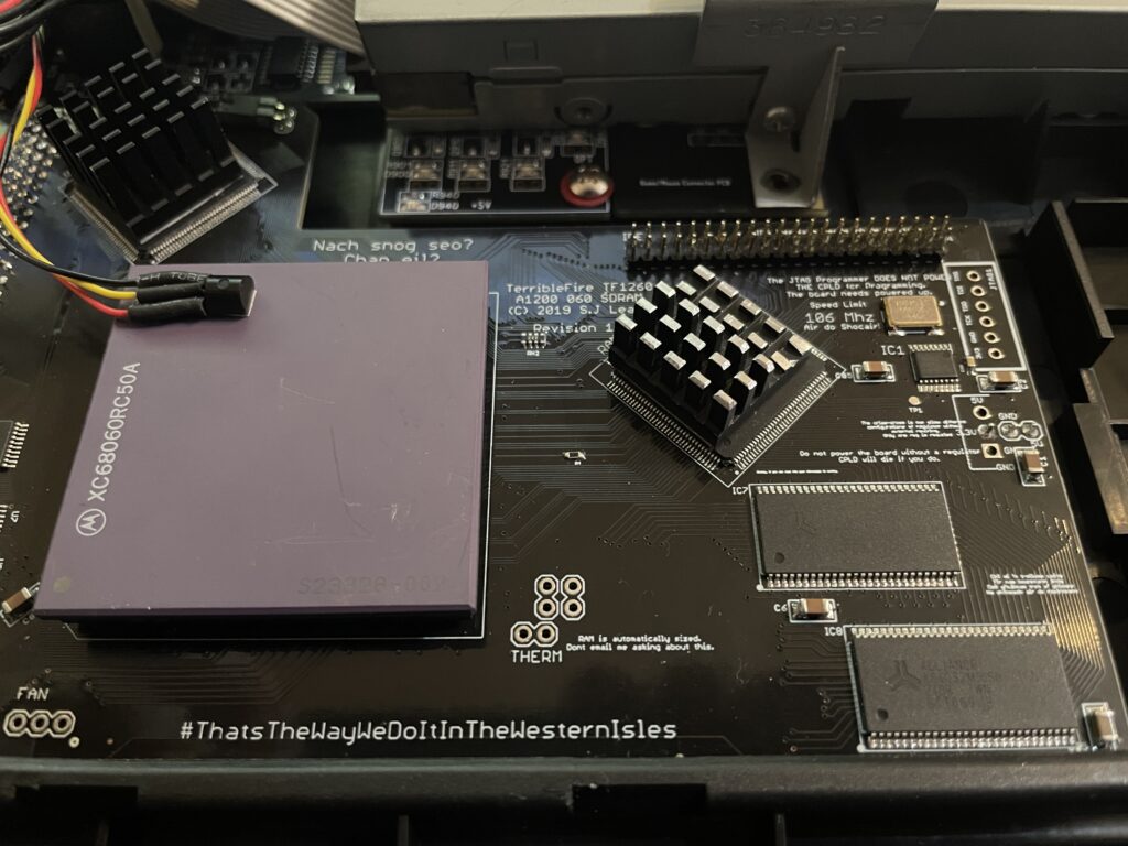
Here I am test fitting the heatsink.
And here it is secured to the chip. I use a thermal pad from AlphaCool that I cut to fit myself. The thermal pad from AlphaCool is somewhat thicker than what you usually get when you order heatsinks from Aliexpress. The thicknes is 0.5 mm, the thermal pad is also softer and more gooier than regular flat thermal pad. Once secured with the AlphaCool thermal tape, these pads wont go anywhere, they are secured very firmly. I highly recommend these AlphaCool thermal tape and would use them even on the 060 with a large heatsink without no problem or worry that the heatsink would fall off (even if mounted vertical!)
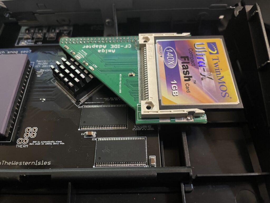
So here we are, everything fits now. But to use the IDE port on the TF1260 I need to burn a custom Kickstart with ehide.device, more on that when I will get to it.
And about finding a solution for cooling down the 060? I have not got a clue, I will probably need to cut down a thin copper plate and place a heatsink on it offsett from the CPU. Not ideal, but better than nothing. A small heatpipe cooler leading heat to fins over the top of the cards close to the floppy drive would be ideal, but prototyping a cooler like that would take weeks and lots of money. I will see what I will come up with.
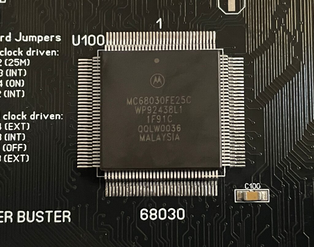
Motorola 68030 25Mhz on the A3000D motherboard (ReAmiga 3000 SMC version)
I am working on a ReAmiga 3000 motherboard. I am in no rush to finish it, taking it really slow ordering one set of parts at a time. Last week I got the 68030 so I decided to solder it on the motherboard this weekend. Hopefully I will be able to do a test drive before Q1 is over!
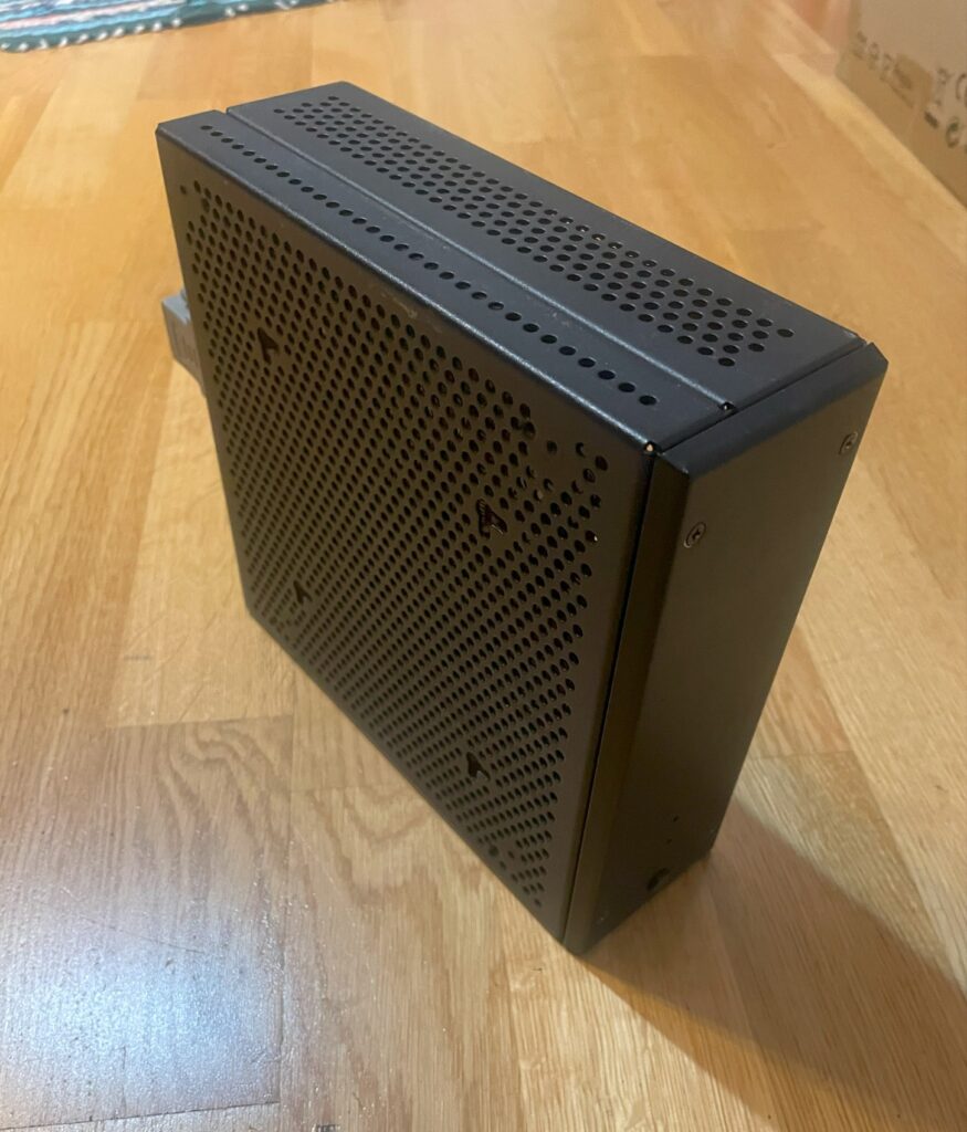
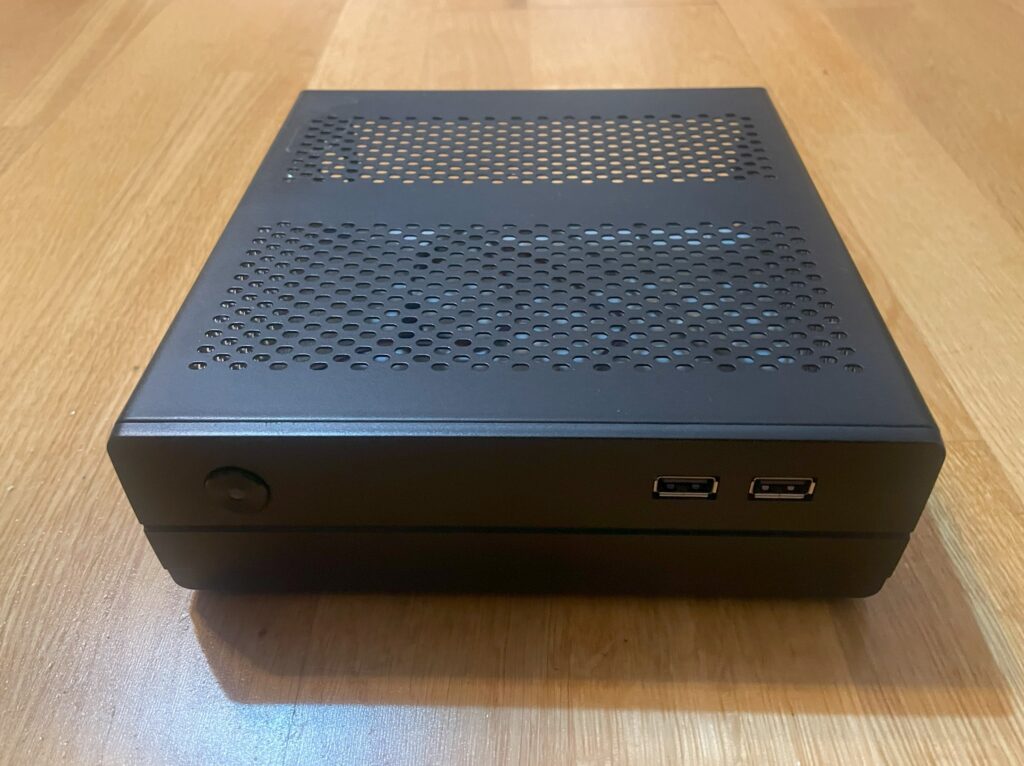
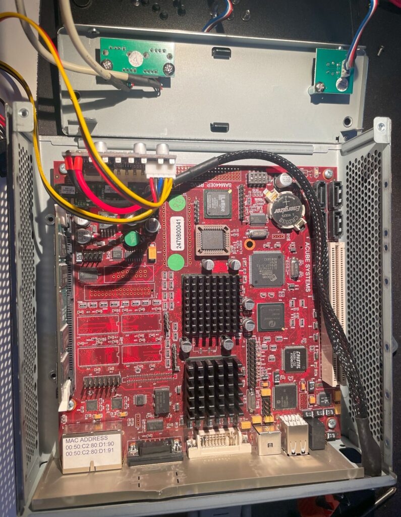
My Acube Sam440ep motherboard that I have been running AmigaOS4.1 on has been installed in this beautiful Emko case (see picture below) for the last couple of years. I wanted to swap cases with one that had front mounted USB ports since the Amiga Sam440ep motherboard only has two USB ports on the back side (and those are used by the keyboard and mouse).
Here is my Sam440ep mounted in a case made by Emko
Emko is a Czech manufacturer of cases, sadly it does not seem they are making cases for private persons any more, but a couple of years ago they had quite a large offering of small Mini-ITX cases that you could buy. I picked up two of them back then, the one on the picture above and the slightly taller version of the same case. They also had a similar case as the one above available in aluminium, I should have picked that one up when I had the chance, c’est la vie…
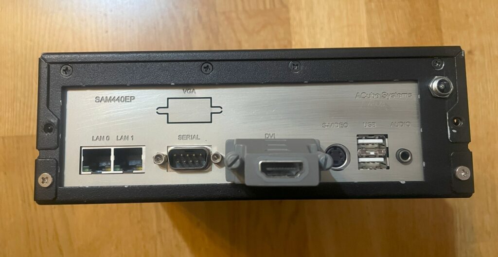
Back of the Sam440ep with the steel backplate
Here is the back of the Emko case. As you can see the Sam440ep does not have many ports. There is a serial port, DVI port, S-video port, audio out, two USB ports and two ethernet ports. Not all of these ports are usable in AmigaOS4.1 though. It is possible to hook up more USB ports from the motherboard also. Acube kindly sent the backplate to me for free if I paid for shipping.
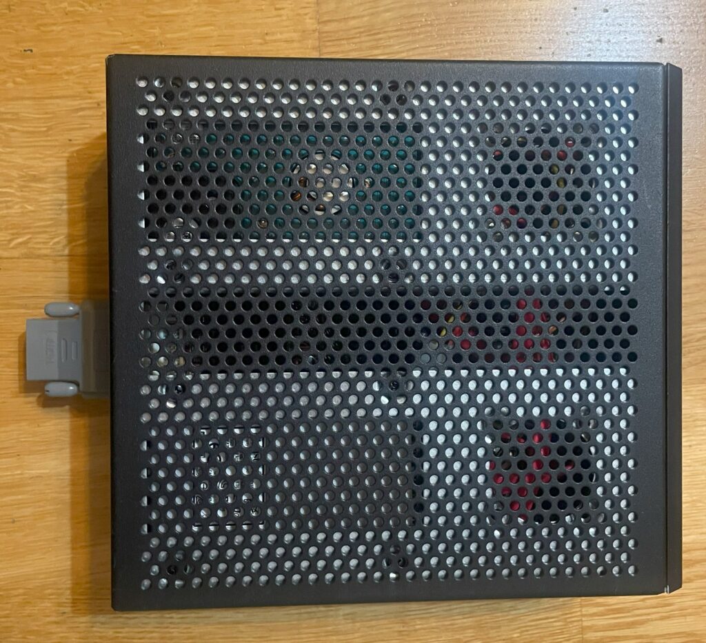
The case offers generous ventilation
One of the best things with the Emko case is its well ventilated design, this is a beautiful case for fanless systems such as the 533MHz Sam440ep motherboard.
Migrating the Sam440ep AmigaOS 4.1 motherboard to the Morex 557
Morex 557 mini-ITX case
I have had my eyes on the Morex 557 Mini-ITX case for a while and was happy finding a second hand unit for sale locally. The Morex 557 is a small ITX case, not that much larger than a Mini-ITX motherboard (and actually just a tiny bit smaller than the Emko case). I suspect these type of cases will be much more difficult to find in the future thanks to the popularity of ITX gaming rigs where you need space for a graphics board so if you like small ITX cases, time to hoard up.
Step 1 – Dismounting the old case
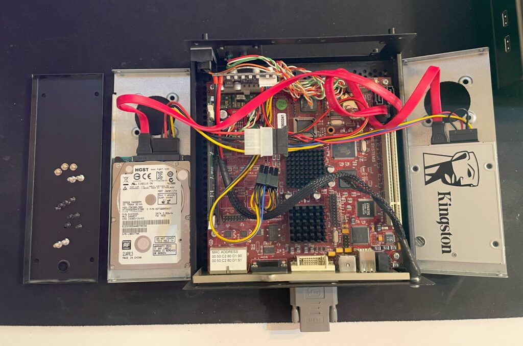
There are a lot of screws to unscrew to open up the Emko case
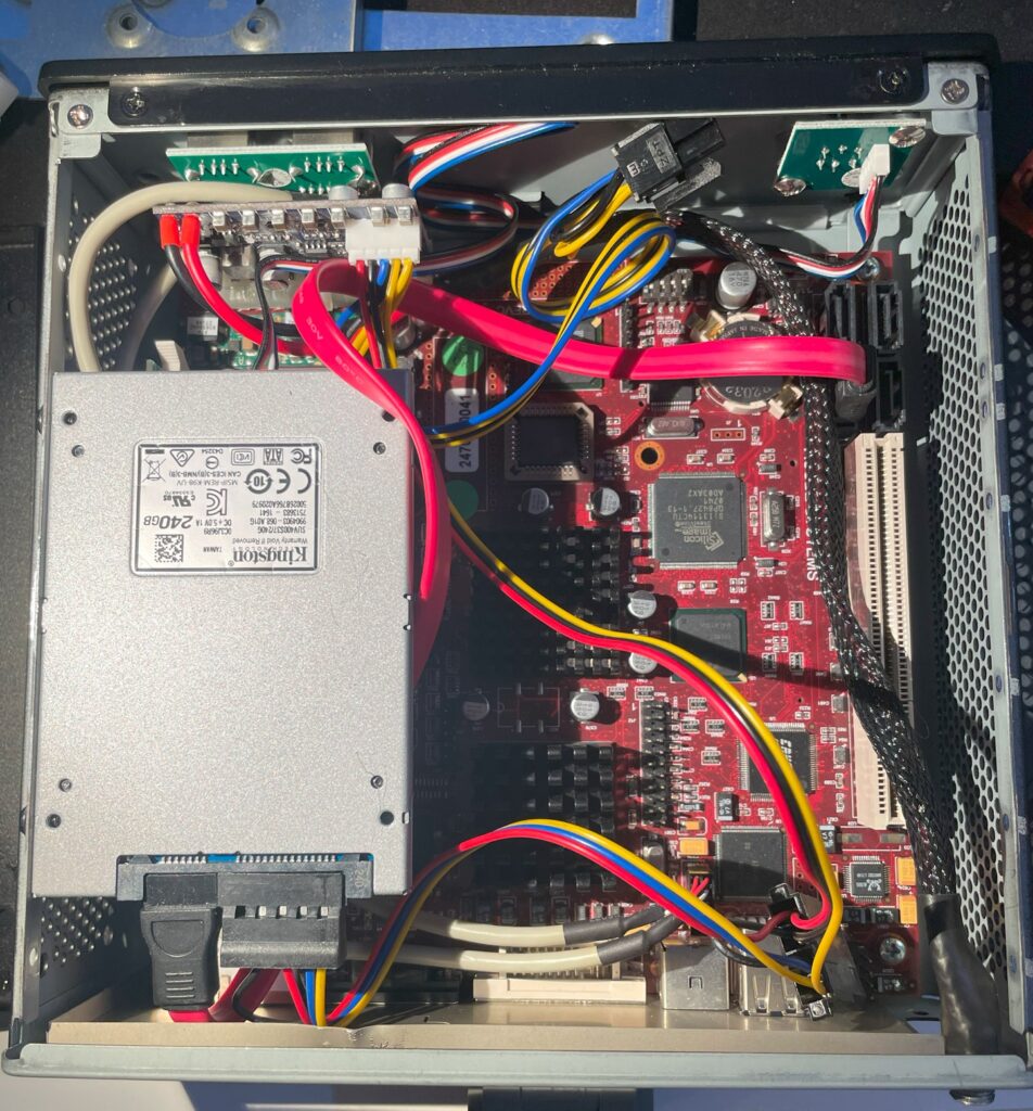
I have set up the Sam440ep with two drives, one 256GB SSD for the Workbench and Work partition and one old 2.5″ 500GB HDD as a data drive. I had this idea to get a larger drive and migrate all Amiga stuff I have to the HDD. That way I would have a backup of all my Amiga hoard of files. That proved difficult though as the FTP program crashed no matter what I tried. Will give it another try in the future but I will definitely retire the slow mechanical HDD sometime in the future.
Step 2 – Prepare installation in new case
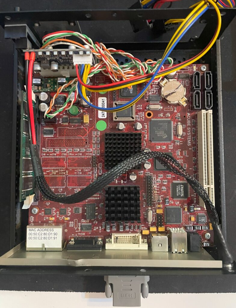
Close up of the Sam440ep Next generation Amiga motherboard
The motherboard is a bit dirty, I did not have enough IPA to clean it though, so next time maybe. If I remember correctly, the upper heatsink sits over the CPU and the bottom heatsink sits over the GPU. The 533MHz Acube Sam440ep can run fanless. Believe it or not, for regular Amiga stuff, 533MHz is fast enough. AmigaOS4.1 definiely does not feel slow on this modest next generation Amiga.
Step 3 – Installation in Morex case
The Morex 557 case was a really tight case, the front had to be removed to get the motherboard into the case. Also note the USB headers on the motherboard, they where not keyed so I had to look up pinouts.
Step 4 – Adding SSD and harddrive to the Sam440ep
It was not obvious where to put the storage drives at first – There was holes on the side of the case for 2.5″ units. Here is the SSD mounted to the side with two screws only, it was a tight fit but it aint going anywhere now.
And here is the 500GB harddrive mounted. I will run this until I find a good replacement. This drive has a bad habbit of spinning down which makes it slow whenever you need to access it again, no idea how to disable that and a good reason to get rid of it in the future.
As you see, with both drives mounted there is still space between the for heat to rise and escape the case.
Some words about AmigaOS 4.1 before closing this post…
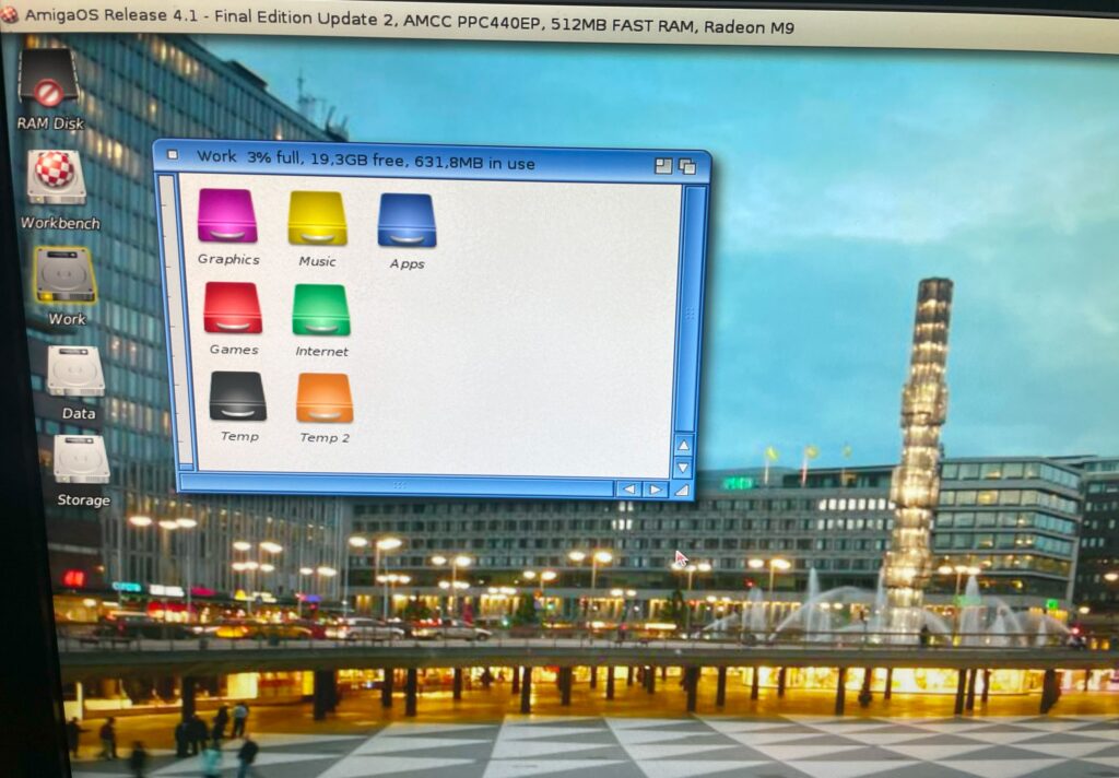
AmigaOS 4.1 Final edition
So the reason for all this is to run AmigaOS4. The Sam440ep motherboard came out in 2008 (or was it 2009), even back then it was obsolete by PC standards. That it cost as much as a much higher perfoming PC of its day made it a hard sell for those outside of the Amiga community and not sold on Workbench.
But the future was bright back then, thanks to the Sam440ep. Because of legal problems, there had been no new next generation Amiga hardware released for quite some years. The released of the Sam440 changed that and that created a lot of excitement and hope for a bright future for Workbench (or AmigaOS depending on what you want to call it).
The Sam440ep was the first batch of AmigaOS 4 compatible hardware released by Acube that lead to renewed interest in the next generation Amiga PPC platform. Unfortunately as we look back today, PPC was probably not the right way to go for the Amiga.
The future of Amiga here and now is probably ARM and Workbench 3.*, not PPC and AmigaOS 4.*.
Thanks to PiStorm, anyone can have a high performance Amiga with “full” compatibility with 68k applications, so IMHO the future of AmigaOS 4 is sadly bleak. But that does not and should not stop anyone from using it (or developing it further).
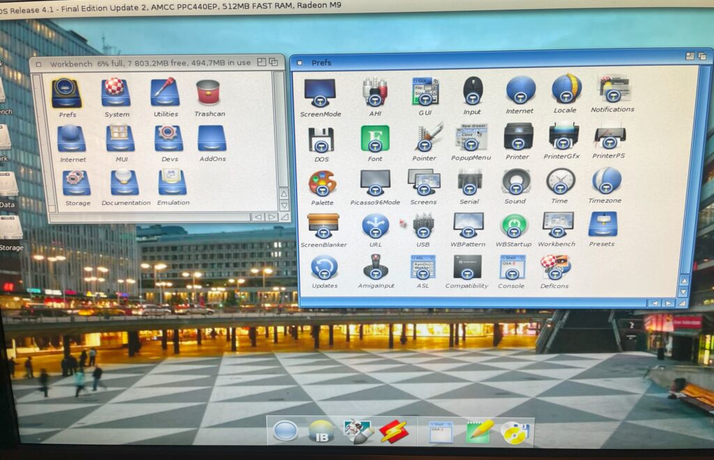
AmigaOS 4.1 showing Prefs
One of the advantages of a next generation Amiga Workbench is that its a much more updated version of the Amiga operating system, both from a software and hardware point of view. There is a TCP/IP stack included, AHI is standard and fonts look amazing on Workbench for example. At the same time, hardware is complete, relatively modern and reliable.
But installing AmigaOS 4.1 is a sharp reminder that we are still in the early 90ies. Configuring AmigaOS to your liking from the first installation is a reminder of how far general computing has gotten in comparison with the “modern” AmigaOS.
There is a lot of clicking and editing files to get it custom tuned to your liking.
Prepare to sit off a couple of days to get it tuned to your liking. Sadly Prefs is unfortunately just a mess by modern standards.
But when AmigaOS 4.1 is fine tuned to your liking, it is perfect – And most of the stuff is exactly where you expect it to be and where it used to be. That is the huge selling point of AmigaOS4, but also a dead end!
The best thing is, you can get it today (and pretend its 1995 again).
Someone said that AmigaOS4 is for hardcore Workbench users – I can not agree more!
This is what every Amiga fan was dreaming of back in 1995 -An Amiga running on a modern CPU with a ported operating system-. The best thing is, you can get it today (and pretend its 1995 again).
Closing off, my primary use of my Sam440ep next gen Amiga is for PPaint, there is a PPC port of it that runs beautifully on the Sam. If there was a modern browser capable of the modern web available I would not mind running a higher performance next gen Amiga as a daily driver.
The final Amiga hardware project of the year for me is this nice mini hardware kit for the Amiga 1200, the OpenA1200RTC. A real time clock that you can hook up to an Amiga that has a clock port. Find out more about the OpenA1200RTC here. The real time clock makes the Amiga 1200 keep track of time.
Building the OpenA1200RTC
This was a very simple 20 minute build containing only 13 parts. The only moderately difficult to find part is probably the RTC chip which can be found on Ebay or AliExpress.
What is the clock port in an Amiga?
The Amiga 1200 has a port famously dubbed the “clock port”. The clock port is a 2 mm double row 22 pin header close to the CPU slot. It was rarely used for its intended purpose, to host a real time clock, since hardware engineers figured out how to hook up sound cards, serial ports and other things to it.
There are some Zorro cards that also has clock ports. That means it is possible to run clock port hardware on a big box Amiga that can carry Zorro cards.
So what do you use an RTC for anyways on an Amiga?
The main purpose of having an RTC such as the OpenA1200RTC is for the Amiga to not lose time when it is powered off. Having your computer keep track on time is not only usable for having a clock on the desktop. If the computer keeps track of time, that means all files will have timestamps for when they were created or last edited. It is possible to sync date and time with a server over the internet but it could be handy to have an internal RTC on an Amiga that is not hooked up to the internet a majority of time. Also, it could be nice to finally use the clock port for its intended application once.
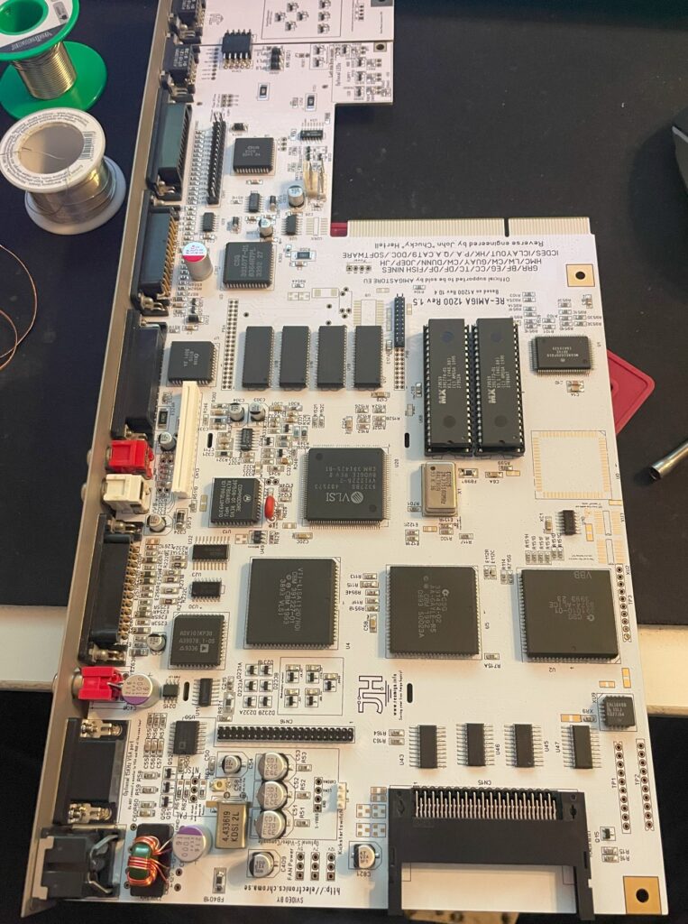
I built a ReAmiga 1200 late last year using a black PCB. Once built I knew I wanted a backup ReA1200. I usually build systems in pairs, one for usage and one for backup or testing purposes. I always have a purpose for stuff I get since I do not believe in hoarding up stuff for hoarding purposes only. I am not into this just to build a huge collection to gather dust.
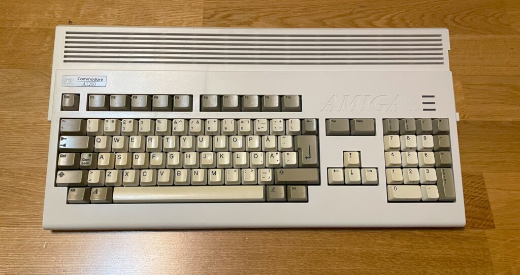
The first ReAmiga 1200 I built had a black PCB and is running in a black A1200.net case so I decided to go for another color than black this time. The only color I found, since I did not want to order a batch of PCBs myself, was white so thats what I got.
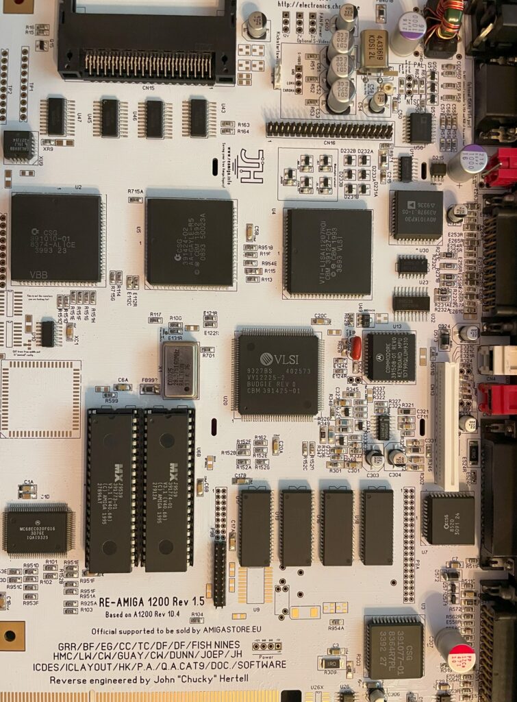
Closeup of the white ReAmiga 1200 motherboard
As with the last ReAmiga 1200 PCB I built this build went really smooth. I used components from a broken A1200 PCB that I desoldered with an hot air rework station. I also got connectors from that donor board. Other stuff like the PCMCIA connector and the odd chip here and there was ordered from AliExpress, Sordan and from ebay.de.
Of course the majority of passives and some chips came from Mouser. This time I used the same color for all LEDs -green- unlike my last one that has a mix of different colors. I sort of wish I got red LEDs instead of green, perhaps if I build a third one (j/k).
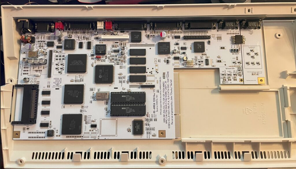
The ReA1200 motherboard is installed in the original Commodore A1200 case
I was thinking of keeping this PCB in storage or getting a white A1200.net case but then I remembered that I had a genuine Amiga 1200 case I got before. Most A1200 cases are in bad shape these days but this one was actually in relatively fine shape. Notice the Centurion tech backplate that I used instead of the metal shield. It looks much better than the flimsy original shield.
Even the floppy drive and cables was original (not the screws though)
As a bonus, that case had all the parts to make it a full A1200. The floppy drive, cables, LED lights for HDD, floppy and power and the keyboard.
Here is the ReAmiga 1200 fully built in the Commdore A1200 case with orginal keys.
And believe it or not, the plastic threads for the screws was not stripped or cracked. The keyboard was relatively white too and had not gone too yellow over the years. Testing the system (there is no HDD inside it) it works fine and I actually did have a plan for this system, sometimes in the future when the scandoubler arrives for the PiStorm32 I will try PiStorm32 on it. But as it stands right now its going into my storage.
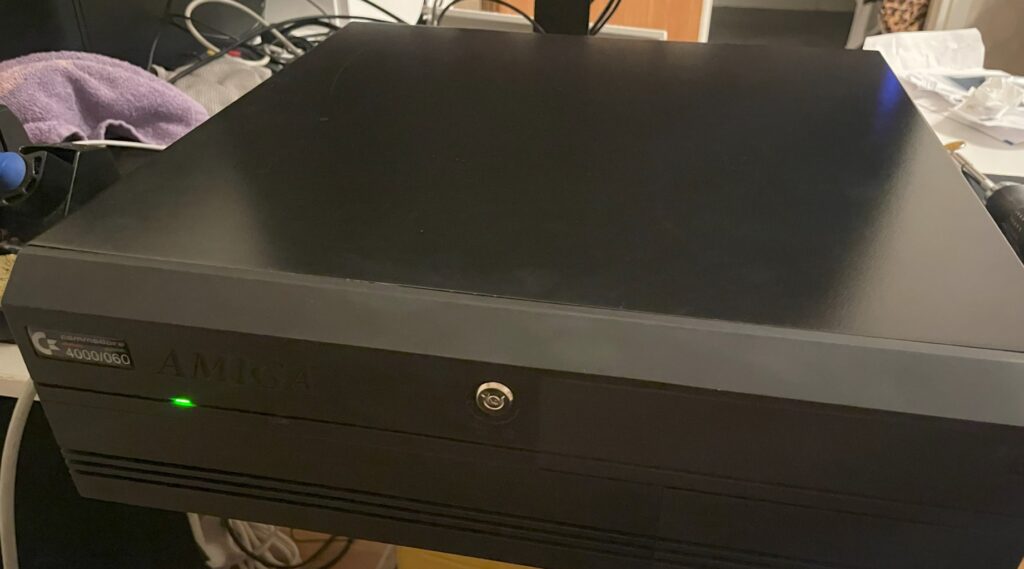
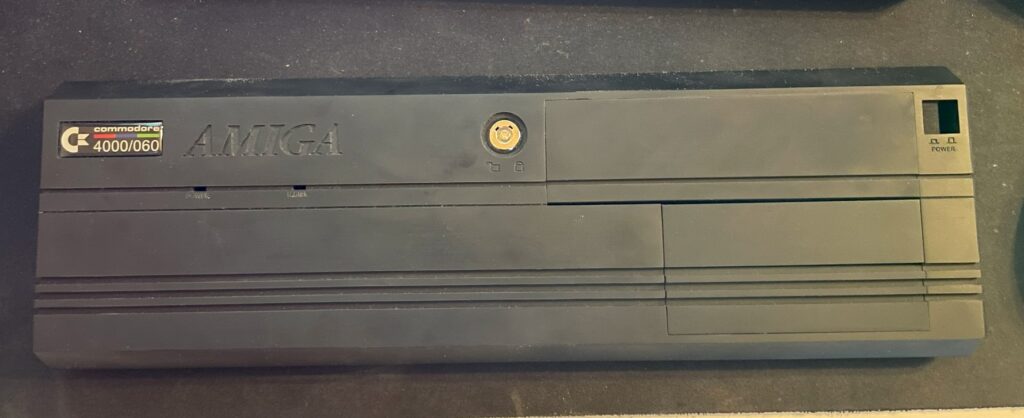
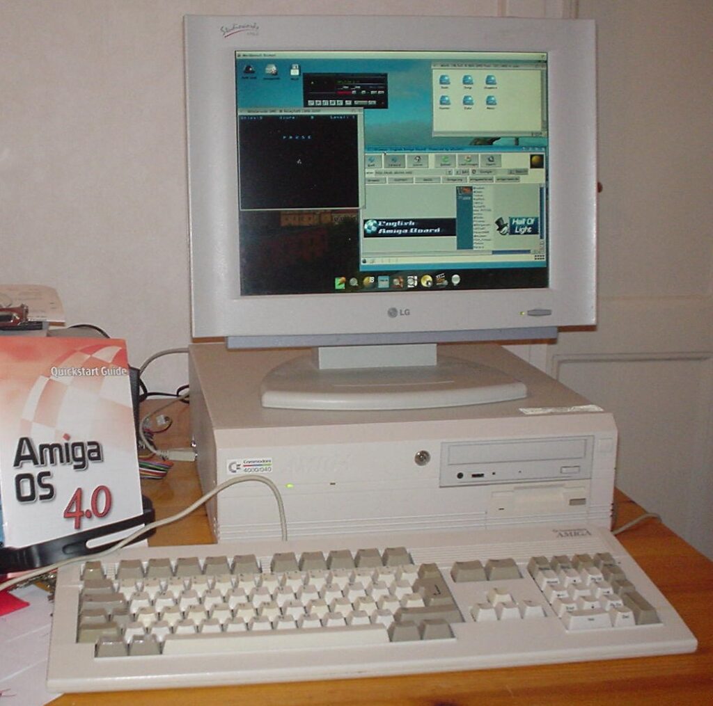
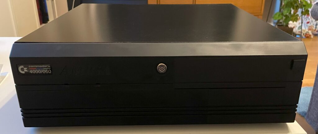
Here is my black Amiga 4000D with a green power LED
I bought a replica Amiga 4000D case off of Amibay earlier this year. One of the joys of building and buying clones and replica hardware is the challenge of finding parts you need. In this case, I needed a front for the A4000D. Thankfully there was 3D model you could download and 3D print that solved the problem, but it did not came with LEDs or the keylock so here came another challenge: find the correct parts for the LED, how to mount them and where to find the keylock.
Amiga 4000D LEDs
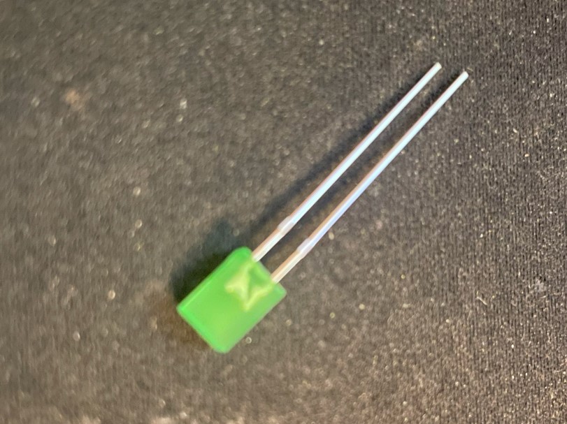
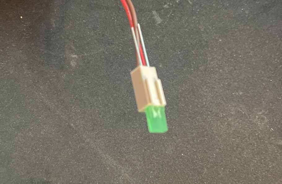
Amiga 4000D front panel LED
So the LEDs are standard square, flat 5v LEDs. These can be found in most electronic shops, here is a link to the green ones I bought. I think green looks fine, there was yellow and orange also and probably blue if you look around. I am not that fond of blue leds so green was it.
A4000D uses a two pin Molex connector and a flat LED
The LEDs are mounted to two terminal Molex connector (2.54mm). The Molex connector slips into the opening over the cable sleeves. If I remember correctly this is actually how they are setup on a genuine A4000D. On the picture above you can see the long pins of the LED sticking out through the back of the Molex connector, I cut these off and bent them over the Molex connector afterwards.
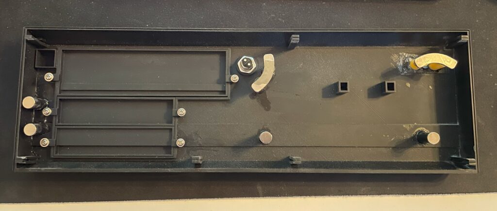
There are magnets on the back of the A4000D front that holds it to the chassi.
Here you can see the 2 pin Molex connector placed into the holes for the LED. On an older A4000D I had (a genuine one) I put a dab of hot glue on them to hold them in place, perhaps I will do it on this A4000D replica too in the future, but for the moment they stay fit on the A4000D front with no problem. You can also see the cables, they are soldered to three pin 2.54mm connectors. One pin is left out.
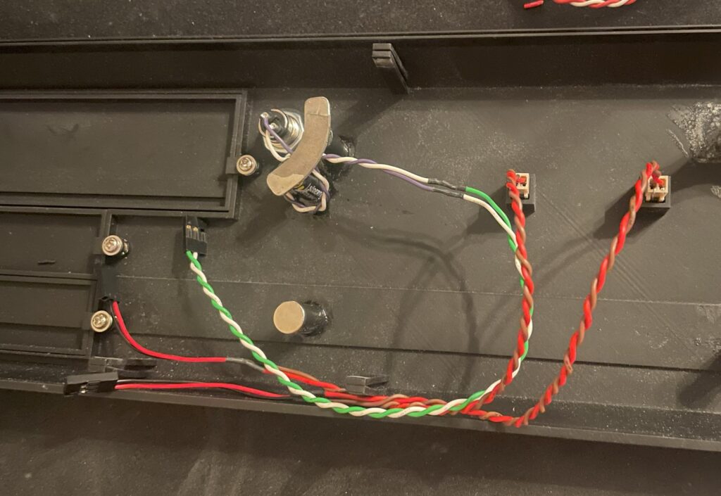
Cables are inserted to the A4000D motherboard
At first the LEDs did not light up, so I just switched positions on the cables and then they worked as they should. If you look at the A4000D motherboard circuit to the pinouts, you can see that the middle pin is unique, but the two outher pins are the same (hooked up together). So if you have the correct polarity you can flip them around and they should work.
Amiga 4000D keylock
Amiga 4000D front with keylock
The Mouser part number for the keylock is, 612-KO132A1501 – here is the page for it on Mouser. If I remember correctly the keylock does not disable the A4000D from working, it just disables the keyboard. And to be totally honest, a keylock in this day and age is kind of pointless, however the A4000D front would not look correct without one, so I “had” to get one. I just soldered two wires to the terminals of the keylock and hooked it up to the motherboard.
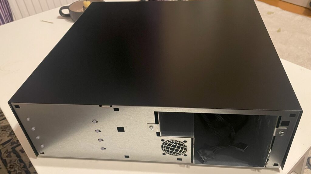
I bought a replica Amiga 4000D case earlier this year on Amibay. It is really good clone of the A4000D case with the exception it has slightly better cooling, space for a 40 mm fan, was painted black, has some options the original Commodore A4000D did not have, uses an SFX ATX PSU and did not come with a front panel.
I really like the look of the A4000D (even if it is just a lousy PC case that was adapted to the A4000D in the last minute), especially the front panel. If there is a template for a professional early 90ies computer case, I think this could be one of them (together with SGI, Sparcstation and so on) – There is just something about the angled look of it and the Amiga logo inprinted in the case cover mold.
Functionality wise, the case is a disaster. The Amiga 4000D case has lousy cooling. The whole case depends on the fan in the PSU to cool the whole system. There is no active cooling at all on the Zorro board section. It has the mouse and joystick port awkwardly mounted on the side making it difficult to remove the cover. And while it has a 5.25 slot, it is too shallow and wont take a full length CD-rom (or DVD). Many of these problems has been solved in the replica case and many of these problems are not problems anymore (I never want to touch optical media again).
What about the A4000D 3D printed front panel?
Its a bit dusty in the picture but the finish is really smooth
The files for the 3D printed A4000D cover can be found here. You can find the different 5.25 and 3.5 cover slots there too. I got them printed at JLCPCB in nylon resin and something, I have forgotten, I also got the power button on a stick 3D printed. All in all the total cost was somewhere around 50 euro, very affordable IMHO. The front was printed in one piece. It has a bit of a rough look to it if you look close, but it is surprisingly well done. I do like the rough look as it resonates with the home built A4000D motherboard, its not perfect as in a factory made case/computer as it is DIY built.
However, the front panel do not fit on the A4000D case that good. The clips are too long and they are really soft and became slack quick, meaning the front panel hangs off the front of the case and just looks cheap.
How I got the Amiga 4000D 3D printed front panel attached to the case
I had an idea to use strong neodymium magnets to hold the front cover onto the A4000D case.
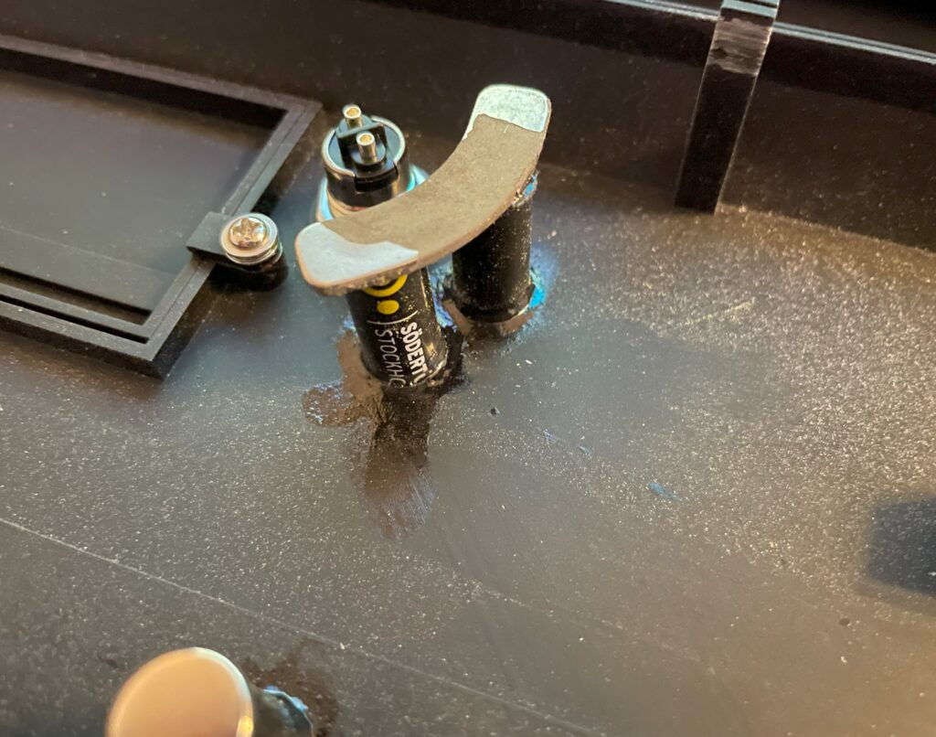
In the picture above you can see four round magnets and two banana shaped magnets. The banana shaped magnets came from an old 3.5″ harddrive that I recycled. These magnets are really strong.
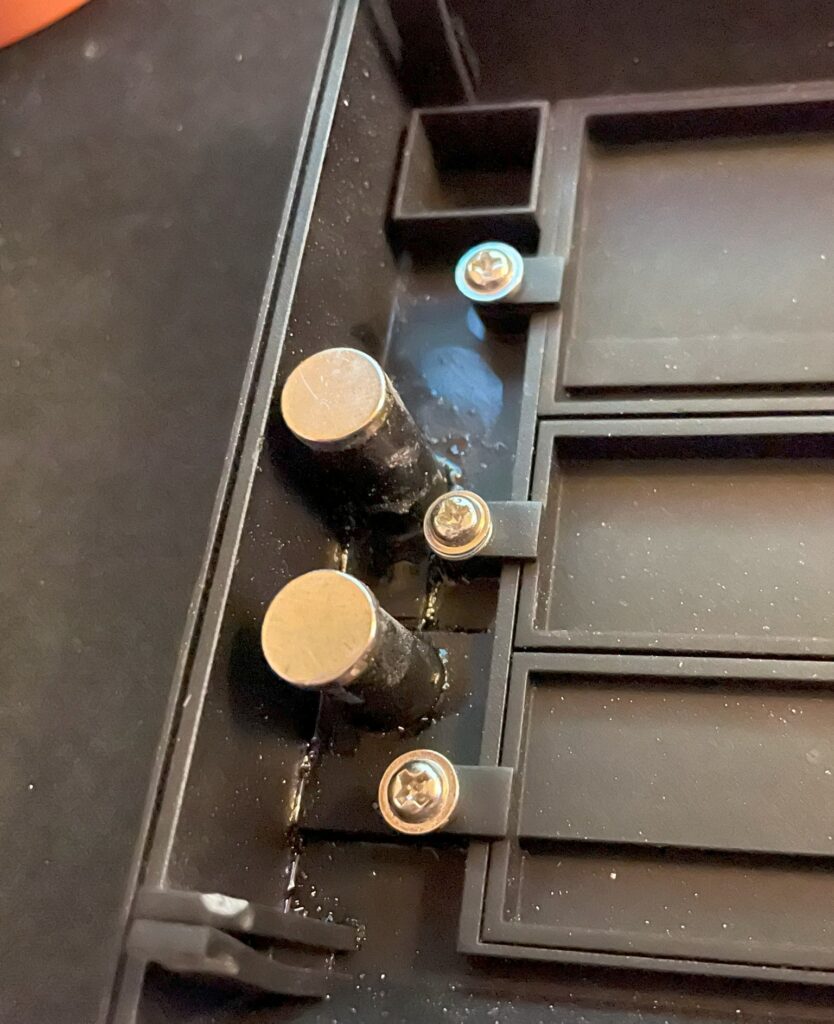
The round magnets are also neodymium magnets but less strong. If I was to start over I would just use three of the really strong banana shaped magnets they hold the 3D printed front panel to the case strong and secure. See the peg in the bottom left corner and how it has sagged.
It looks a bit sloppy because it is, I will paint the stand offs for the magnets black and maybe even add some black bondo to them to make it look nicer. However as a proof of concept everything works and is secure. The stand offs are regular plastic pencils that I cut to lenght and then super glued to the 3D printed A4000D front, I then super glued the magnet to them and let everything dry over the night.
I thought that the magnets would work themself loose from being super glued to the stand offs but I have been proven wrong. They are secured to the stand offs and case and wont move or brake off.
Here is the case with the cover added to it, being held to the case just by the magnets. Taking it off the case needs a lot of force. To make it easier I sanded off the hooks on the pegs of the front cover to make it easier to slide out the holes of the front of the case. Again, looks rough but works fine.
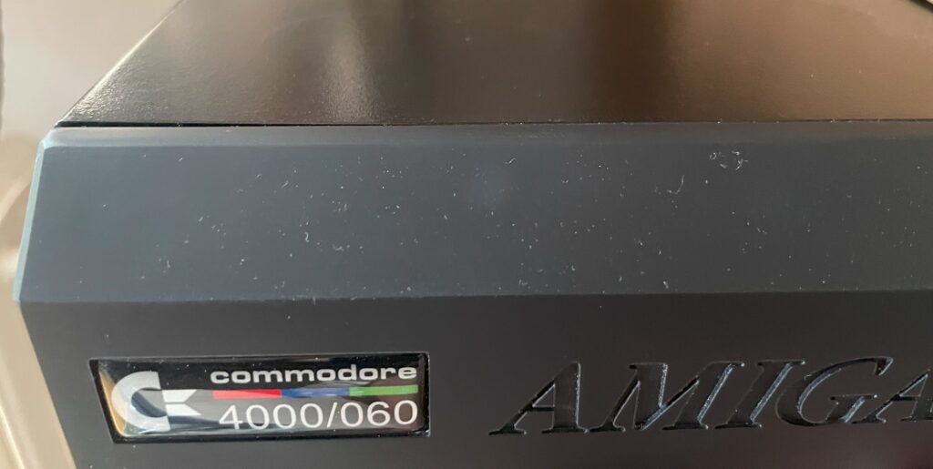
Here is a closeup of the 3D printed A4000D front cover, the badge was bought from a store online.
All in all I am very happy with my black A4000D case. I think it fits into a modern office much better when it is black as so few computers come in beige these days.